SEIS’s deployment on Mars (I)
Deployment of the first seismometer on the Martian surface by the InSight lander (part I)
Following the successful positioning of the SEIS seismometer on InSight’s landing site on 19 December 2018, mission engineers and scientists completed several key steps in this exceptional instrument’s commissioning process. Whether on Earth or Mars, the quality of a seismometer’s installation is crucial for it to operate at its best. On the Red Planet, however, operations have to be carried out remotely by robotic devices, which requires a combination of great expertise, care and... as you will see, a good dose of patience!
Characterization and certification of the deployment site
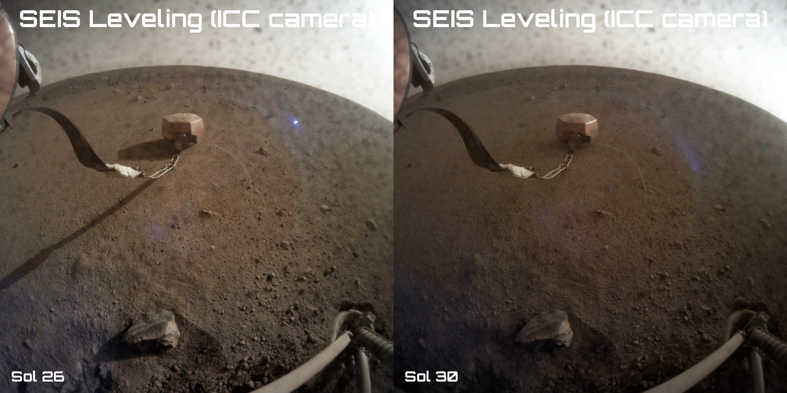 Animated sequence of images taken by the instrument context camera (ICC) showing the levelling operation during sol 30 (© NASA/JPL-Caltech).The SEIS instrument remained switched off throughout its historic deployment on Elysium Planitia during sol 22. When the seismometer was switched back on during sol 24 (20 December 2018), the short-period (SP) sensors sent back to Earth the first seismic data ever obtained from the Martian surface, 42 years after those provided by the Viking 2 mission’s seismometer operating from the lander deck on Utopia Planitia. The Viking spacecraft’s seismometer could only operate from the deck because the lander was not equipped to deploy it on the actual surface.
As soon as they were activated, the SP sensors obtained preliminary data with little noise, despite the fact that the robotic arm’s gripper was still holding the instrument’s carrying handle, thus inevitably transmitting the lander’s own vibrations. Once they were sure that the seismometer’s three legs were safely on the ground and not still suspended from the gripper, the engineers green-lighted its release. On 22 December 2018 (sol 25), the gripper opened, thus freeing the instrument.
The analysis of new data provided by the SP sensors following this operation and their comparison with those obtained from the lander deck proved that the chosen deployment site was indeed very quiet. On the surface, the daytime noise level is now comparable to the night-time level measured when SEIS was still on the lander deck (wind activity being lower during the night than the day). The site’s noise level is also lower than that of the quietest caves or mineshafts used to record seismic activity on Earth. This is partly due to the fact that the Red Planet has no oceans. On Earth, the pounding of ocean waves creates a constant micro-seismic noise that disturbs measurements.
The next major step in the seismometer’s deployment involved making sure it was level relative to the horizontal. SEIS has six seismic sensors: three short-period (SP) sensors, which do not need to be level to work correctly, and three more sensitive very broad band (VBB) pendulums that represent the very core of the instrument. These sensors cannot supply data unless SEIS is perfectly level.
While the SP sensors were activated in space during the cruise phase between Earth and Mars, and shortly after landing on Mars, this was not possible for the VBB pendulums. The SP sensors had also provided data that was vital for characterizing the noise level, first from the lander deck and then from the Martian surface, but engineers had only been able to partially confirm the VBB pendulums’ operational status. The waiting seismologists were therefore extremely keen for them to be activated, as the VBB pendulums are crucial to the InSight mission’s success. They can probe the planet’s interior to greater depths than the SP sensors and thus provide vital information on its internal structure.
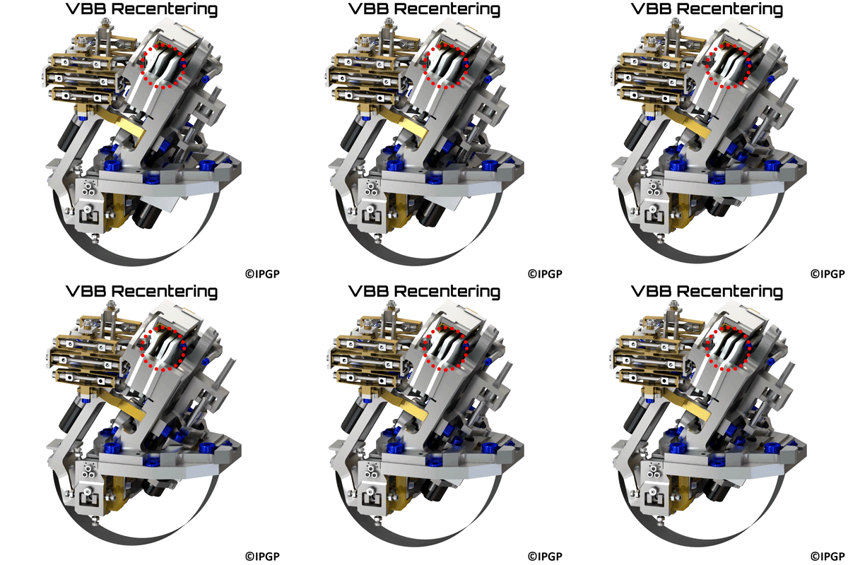 Animated sequence showing how the motorized balancing mechanism centres the VBB pendulums (© IPGP/David Ducros).
The gradients of the deployment site were measured by the levelling cradle inclinometers on sol 25. Fortunately, the surface on which SEIS was placed had only a gentle slope of around 2.5°. The three motorized legs of the levelling system were activated on sol 30 (28 December 2018) to ensure SEIS was exactly horizontal. The algorithm that automatically monitored the operations on Mars found an ideal solution after only two iterations. The levelling operations involved slightly retracting two legs and extending the third one by about 5 mm. The images from the instrument deployment camera (IDC) on the robotic arm reveal this change in the instrument’s inclination.
Recentering the VBB pendulums
Having ensured that the instrument was almost perfectly level and had not moved after one month, engineers from the Institut de Physique du Globe de Paris (IPGP), the French space agency (CNES) and the Jet Propulsion Laboratory (JPL) scheduled the VBB pendulum centring operation. Until then, to protect the ultrasensitive sensors from knocks and vibrations caused mainly by the launch and landing, the moving part of the pendulums was secured next to the end stop. When the VBB pendulums were switched on for checks (sol 4 then sol 30), the sensors were saturated and the data unexploitable, as expected. The engineers knew that the pendulums appeared to have arrived safely on the Martian soil, but did not have any really useful signals.
On New Year’s Day, during sol 35, the balancing mechanism motor was activated on Mars to place the moving part of the three VBB pendulums in their central equilibrium position. The arrival of the first data during the following sol (sol 36, 2 January 2019) at 08:21 was greeted with a torrent of applause from the team gathered in front of the main screen of the SEIS operations room at JPL.
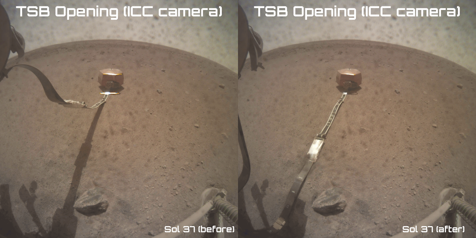 Animated sequence of images taken by the instrument deployment camera (IDC) showing the opening of the tether storage box (TSB) (© NASA/JPL-Caltech).
The VBB pendulum centring operation was an essential prerequisite to activating the SEIS seismometer. The engineers involved had no way of correctly simulating on Earth the gravity found on Mars. Various tricks of the trade were used to test the pendulums under Martian conditions in the laboratory, including inclining the axis at which the pendulums are sensitive by an angle relative to the gravity vector, using a small mass to artificially lighten the sensors, or suspending the instrument from balloons. However, nothing was 100% certain before real-life operation on Mars. One of the fears of engineers was that no equilibrium position would be able to be found on Mars, or that the semicircular spring would be subject to friction. Their calculations proved to be right, however, and since 1 January 2019, the VBB pendulums have been operating correctly in Martian gravity. On the broad plain of Elysium Planitia, all six of the SEIS instrument’s seismic sensors are now not only operational but hard at work.
Deploying the umbilical tether : opening the TSB
Operating for the moment in engineering mode, the VBB pendulums have transmitted many seismic data since sol 36 that have been coupled with those from the SP sensors to characterize the deployment site and more especially the interfering signals transmitted by the tether that connects the instrument to the InSight lander. The lander is vital to the seismometer’s operation because it exchanges data with SEIS and provides its electrical power supply.
However, because of the huge differences in temperature on Mars between day and night (-70°C on average), the seismometer is subject to thermo-elastic deformation that project engineers have to minimize. This phenomenon is a feared hazard of the Red Planet. It does not come into play on Earth because seismometers are set up in environments such as caves or mineshafts, which are extremely stable in temperature (varying by as little as 0.01°C daily). On Mars, however, deformations are so large they can be seen by the naked eye on pictures taken by the IDC. The wind is also a source of disturbance that needs to be removed by acting on the umbilical tether.
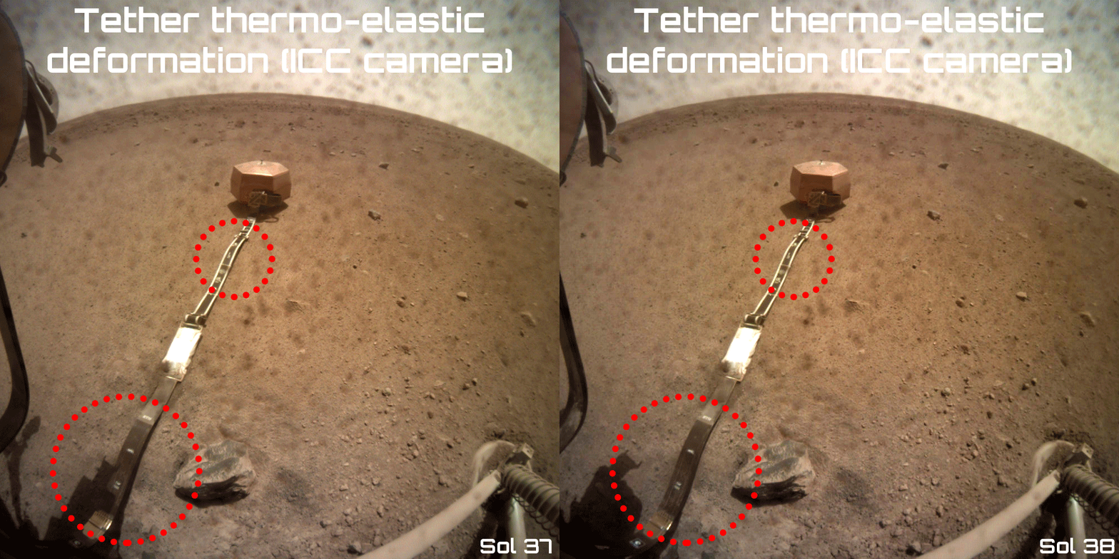 Supposed thermo-elastic deformation of the SEIS umbilical tether on Mars between sol 37 at 13:24 LMST and sol 38 at 14:09 LMST. The logos accentuate the tether’s movement (© NASA/JPL-Caltech).When SEIS was deployed on 19 December, part of the tether was still rolled up in the tether storage box (TSB), a cylindrical box attached to the lander. This was necessary in case the instrument had to be moved to another position by the robotic arm if the first place chosen proved unsatisfactory from a seismic point of view. Data analysis convinced engineers that the TSB could be opened. The operation was successfully carried out on 3 January 2019 (sol 37) once SEIS had been switched off. The images taken by the instrument context camera (ICC) clearly show that SEIS’s lifeline is now lying flat on the Martian surface.
Deploying the umbilical tether : separating the LSA plates
The unwinding of the umbilical tether connecting SEIS to the InSight lander was far from being the end of cable deployment operations, however. On Earth, when seismometers are set up in seismic vaults, technicians wind the cable connecting the instrument to the measuring electronics several times around the seismometer so as to neutralize the disturbances that it can transmit. This forms what experts call a “service loop”. On Mars, the SEIS instrument has an equivalent though slightly different system to play this role.
At the junction of the seismometer and the mains power supply, provided by the ribbon cable known as the “tether”, two metal plates attached by a Frangibolt make the tether form a very small service loop. This part of the service loop, known as the load shunt assembly (LSA), is designed to stop interfering signals from propagating along the cable. The main source of disturbance is the daily dilating/shrinking movement caused by the variations in temperature mentioned above.
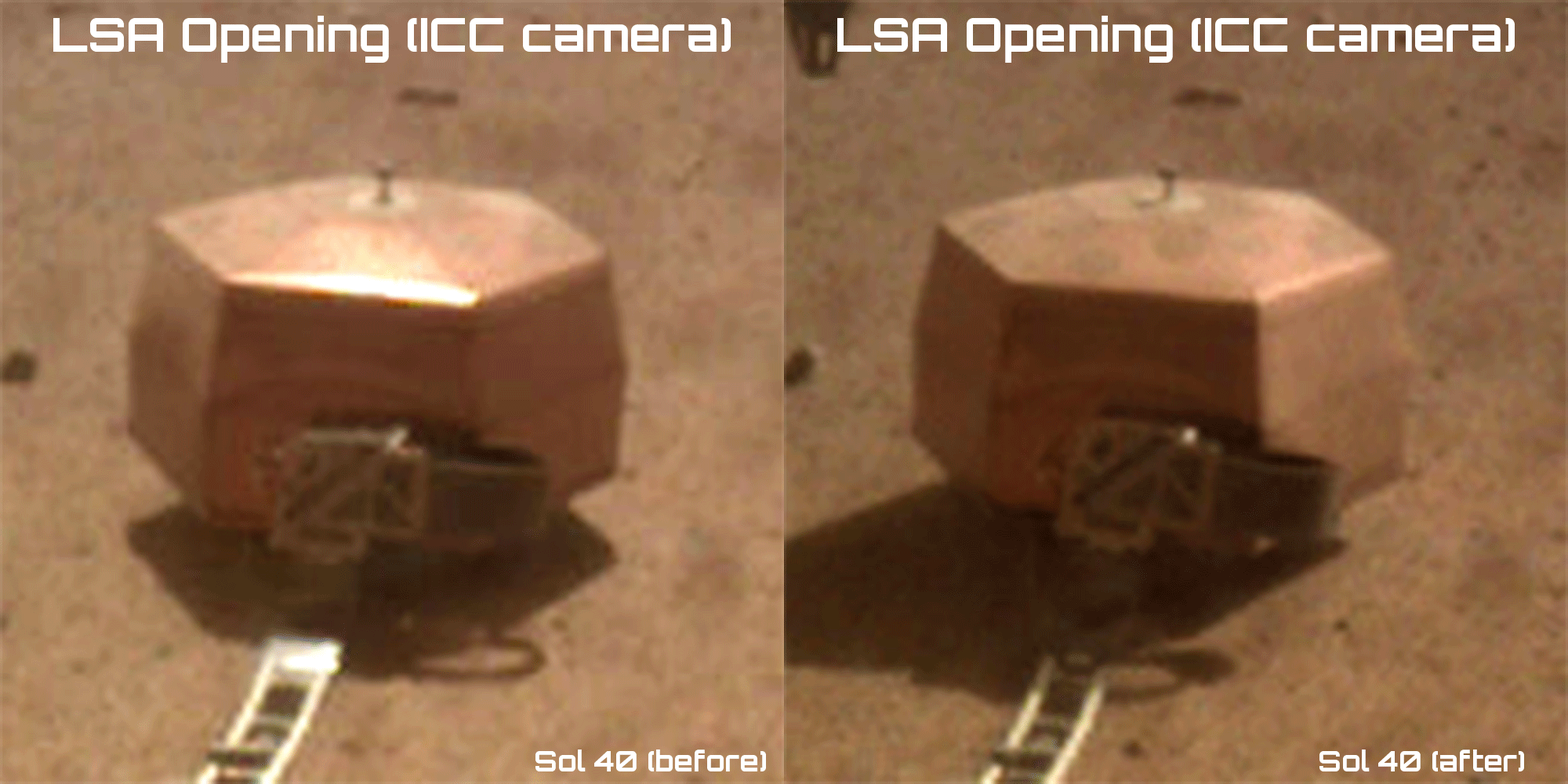 Animated sequence of images taken by the instrument deployment camera (IDC) showing the separation of the LSA plates on Mars during sol 40 (© NASA/JPL-Caltech).
Once the TSB was open, the LSA’s metal plates needed to be separated. This operation was successfully completed during sol 40 (the VBB pendulums having first been placed in their stowed position). As expected, although the two metal plates of the LSA were no longer attached, they were still too close to each other to stop all interference. Engineers needed to increase the gap between the LSA’s metal plates by using the robotic arm to change the cable’s position.
This delicate operation involved positioning the robotic arm so its bucket was touching the small handle on a pinning mass partway along the cable then moving the arm slightly nearer the lander so as to push on the pinning mass and thus move the tether back a few centimetres. The robotic arm’s gripper could also have been used to grab the handle on the pinning mass, but engineers preferred using the bucket for reasons of precision. The option of repositioning the seismometer itself was rejected for many different reasons.
In the second part of this article, we shall look at the results of the separation of the LSA plates before moving on to the final deployment steps: lowering the instrument, placing the wind and thermal shield (WTS) over it, and switching the VBB pendulums to science mode. A little over two months after its landing on Mars, the first seismic recordings from the “ELYSE geophysical station”, as the module is known, really began to reveal the internal structure of the Red Planet.
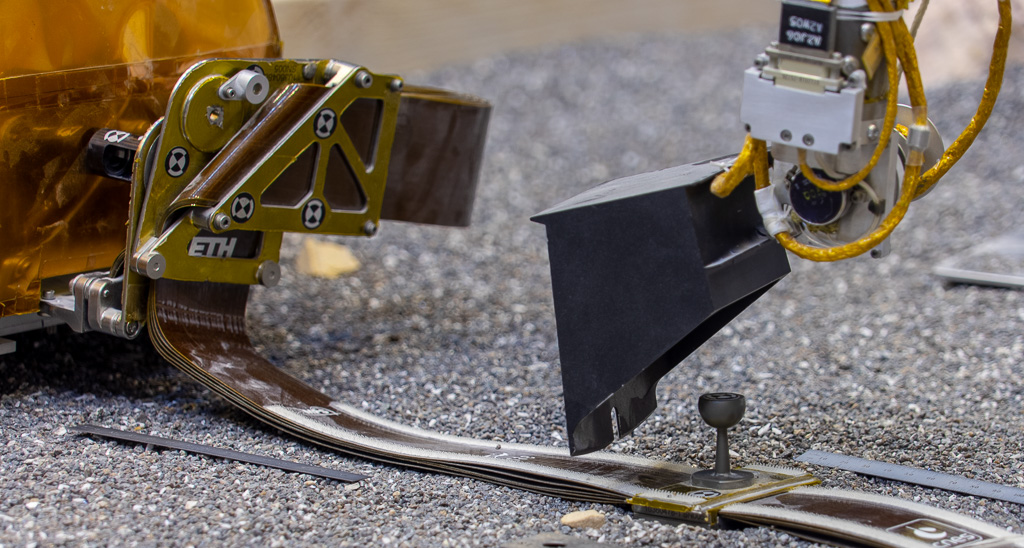 JPL’s ForeSight test bed was used to practise adjusting the position of the pinning mass on the tether between SEIS and the lander using the robotic arm’s bucket to widen the gap between the LSA plates (on the left) (© NASA/JPL-Caltech/IPGP/Philippe Labrot).


