SEIS’s deployment on Mars (II)
Deployment of the first seismometer on the Martian surface by the InSight lander (part II)
The first part of this series of articles on the deployment of SEIS on Mars covered the instrument’s levelling, the centring of the VBB pendulums, and the first steps needed to correctly install the ribbon cable (tether) that connects the seismometer to the InSight lander. This second part focuses on the optimized deployment of the tether, which was far from easy considering it was done via a robot on a different planet! Before focusing on this key operation, however, let us finish looking at the end of the levelling operations.
Lowering and levelling the instrument (“levelling low”)
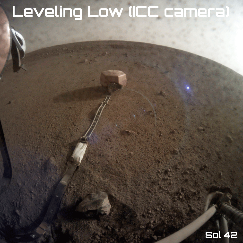 Animated sequence of images taken by the ICC showing the levelling low operation during sol 44 (© NASA/JPL-Caltech).
Following the first unsuccessful attempts at stowing the robotic arm’s gripper (see below), the SEIS lowering and levelling operation (known as “levelling low”), which comes after the levelling operation on sol 30, went so well that it was completed ahead of the initial operations schedule. This step, carried out on sol 44, consisted in activating the three legs of the SEIS levelling cradle to lower the instrument as close to the surface as possible.
This manoeuvre lowered the seismometer by 18 mm in six successive steps. Each leg was activated in succession during the various lowering cycles. The first goal in doing this was to minimize the length of the legs so as to increase their rigidity and thus improve the instrument’s coupling with the Martian surface. A simple experiment will clarify the principle behind this manoeuvre: place a metal dessert spoon on a table with as much of the handle as possible over the edge, and you will see that touching it just slightly makes the whole handle vibrate. If, on the other hand, only a small part of the handle extends over the edge, it is much more difficult to make it vibrate.
The second goal in lowering the seismometer was to be able to place the wind and thermal shield (WTS) over it safely. The SEIS seismometer must never touch the inside of the WTS dome.
InSight plays cup-and-ball on Mars
The last step before positioning the WTS was to increase the space between the two metal plates of the load shunt assembly (LSA) after their mechanical separation during sol 40. A latecomer in the seismometer’s design, the LSA is located on the side. It makes the tether form what is known as a service loop, intended to prevent vibrations and other interfering signals from travelling along it (especially the deformations to which the tether is subject due to the large temperature variations between Martian day and night).
So as to widen the gap between the metal parts of the LSA, the tether had to be moved slightly backwards using InSight’s robotic arm. The bucket was placed in contact with the handle of the pinning mass, attached to the ribbon cable near SEIS. This mass is designed to weigh down the tether and improve its contact with the ground. To position the bucket and slightly push back the pinning mass, the robotic arm’s gripper (deployed during sol 18 on 15 December 2018 once the instruments’ workplace had been fully characterized) had to be returned to its stowed configuration.
This is not as easy as it sounds: the stowage manoeuvre is actually one of the most complicated for the team in charge of InSight’s robotic arm. One of the difficulties lies in the fact that the gripper is connected to the arm by two flexible cables. The most flexible one is the orange power cable. The other one is made of a synthetic material known as Vectran. This white cable is attached to the gripper, and dictates how it is suspended, and its behaviour (swinging or rotating movements, etc.) when the robotic arm moves. Like all flexible or soft materials (from parachute canopies or suspension lines to the flat, semi-rigid ribbon cable connecting SEIS to the lander), this cable is a headache for engineers because its behaviour cannot be perfectly modelled, and it is not possible to manipulate easily.
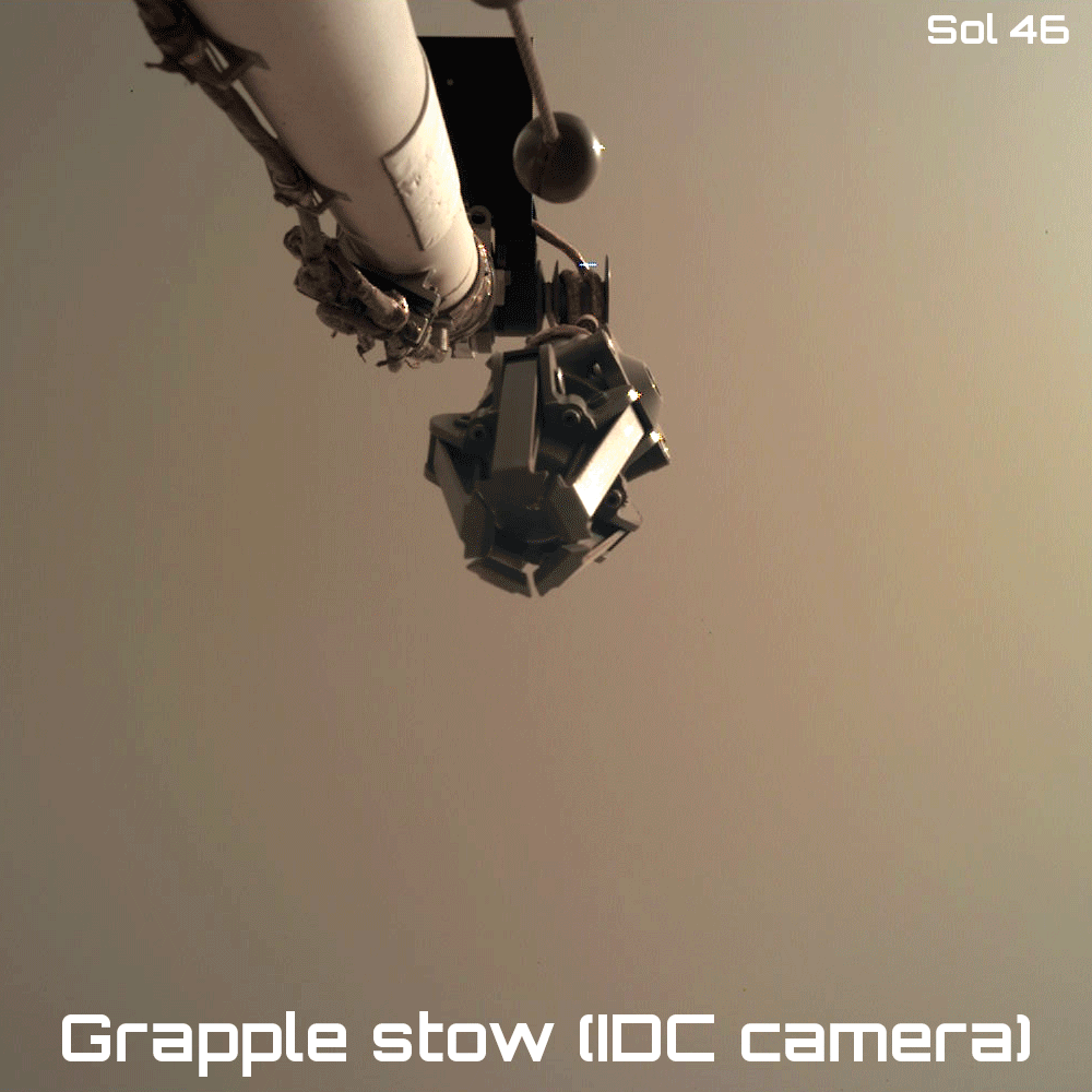 Animated sequence of images taken by the instrument deployment camera (IDC) showing attempts 3 and 4 to stow the gripper during sols 46 and 50 respectively (© NASA/JPL-Caltech).
An initial attempt to stow the gripper during sol 42 proved unsuccessful. Two sols later (sol 44), another identical attempt was made but also failed. The initial gripper stowage manoeuvre consisted of fully extending the robotic arm upwards so the gripper was suspended almost vertically above a small stowage ball attached to the end of a semi-flexible steel rod. After opening the gripper, the arm was to position the gripper right next to the ball. The plan was that by revolving the gripper, its claws would encircle the ball. By closing the claws around the ball it would then be firmly attached alongside the robotic arm.
Although the engineers had successfully carried out numerous tests on Earth with InSight’s twin, the failed attempts on sols 42 and 44 proved how tricky gripper stowage actually was on Mars. There were two main differences between the tests carried out on the ground test bed and the real-life situation on Mars: first, the very low temperatures can rigidify the materials (although this parameter is factored in to the numerical models) and second, the weak Martian gravity can never be perfectly compensated for or simulated. The combination of these two factors can explain the success of the stowage operation on Earth, and its annoying failure on Mars.
To clarify the origin of the problem on the Red Planet, the team in charge of InSight’s robotic arm improved the stowage sequence before their third attempt, on sol 46. They also programmed the IDC so as to obtain a more detailed series of images. Once downloaded to Earth, the pictures clearly showed that once open, the gripper’s claws were still failing to grab the small ball attached to the robotic arm.
A different technique was used on sol 46. This time, the closed gripper was placed right next to the semi-flexible stowage rod first by extending the arm vertically as far as it would go then moving the forearm slightly backwards. It was only when the gripper was actually touching the ball (bending the stowage rod in the process) that it was opened. An additional backward movement of the forearm was then planned to position the five claws around the ball, leading to its capture once the claws were closed. Unfortunately, the forearm was not moved far enough backward on sol 46 so when the gripper was opened it was still too far from the ball and closed again on thin air.
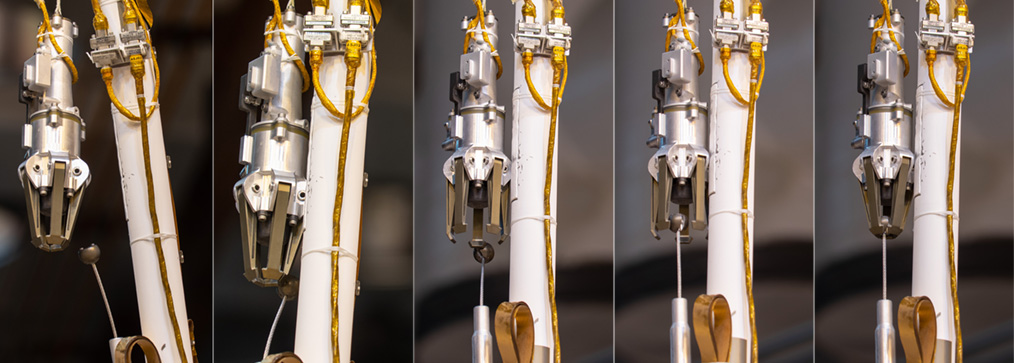 Different steps of the new gripper stowage sequence tested with JPL’s ForeSight lander during sol 48. The gripper and stowage ball at the end of a semi-flexible rod can be clearly seen (© NASA/JPL-Caltech/IPGP/Philippe Labrot).
The InSight engineers went back to the ForeSight test bench to work on a new sequence of commands to stow the gripper on Mars as efficiently as possible. This time, the manoeuvre was divided into two parts: an initial series of operations was scheduled for sol 50 so as to characterize the behaviour of the gripper and the semi-flexible stowage rod. The actual stowage, with capture of the ball, was scheduled for two sols later, although the engineers knew that there was a chance that the gripper would actually capture the ball on sol 50.
The forearm was moved further back than on sol 46. An additional movement was integrated into the sequence after the backward movement of the forearm that allows the five claws to surround the ball, because the engineers realised that when the gripper opened while touching the rod, one of its claws could press against the stowage ball and prevent the gripper from positioning itself correctly above the stowage device. In this case, the gripper could end up closing on the other side of the ball. To obtain a second opportunity to grab the ball, a forward movement was added after opening the gripper again.
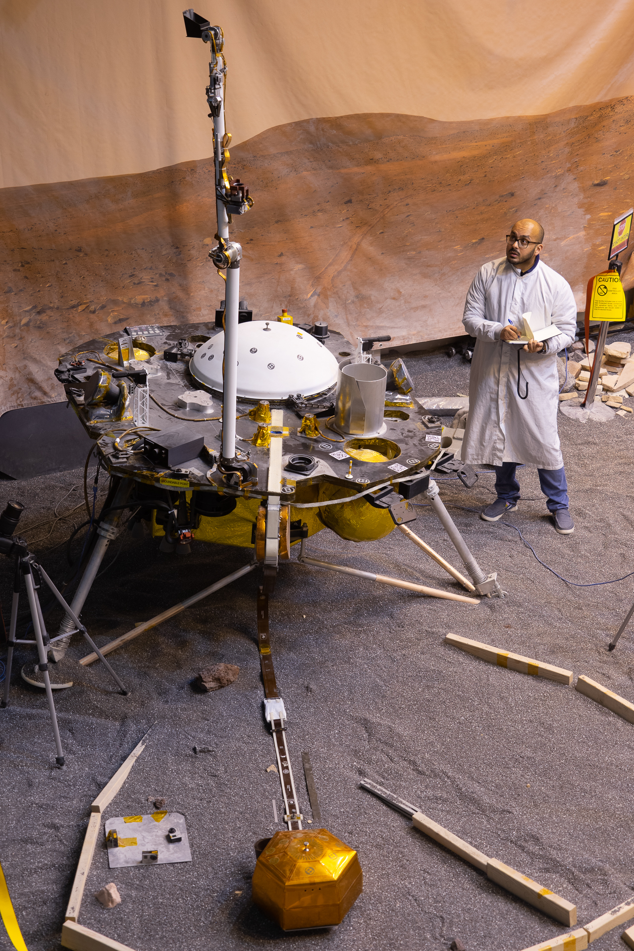 JPL’s ForeSight engineering model with its robotic arm extended vertically when testing the gripper stowage operation during sol 48 (© NASA/JPL-Caltech/IPGP/Philippe Labrot).To make a complicated situation worse, unfortunately operators cannot leave the arm extended vertically on Mars for several sols in a row, which would be useful to be able to start stowage operations then study the images so as to carry out subsequent corrective movements. This is because when the arm is pointed upwards, the IDC is looking right up at the sky, which is a very bad position to be in because dust can gather on the lens. The forearm therefore has to be placed horizontally every sol, which means that the project engineers have to restart stowage operations from scratch every sol.
When the sol 50 images reached Earth, they were greeted with a mixture of relief and satisfaction by the technical team because the ball had been correctly grabbed, as planned, on the first attempt at this new sequence, and the operations scheduled for sol 52 were no longer necessary. If the attempts at gripper stowage had continued to fail, the gripper itself would have been used to move the pinning mass instead of the bucket. During sol 48, tests were carried out to position the gripper above the pinning mass handle just in case this manoeuvre proved necessary. Theoretically, it would also have been possible to widen the gap between the LSA plates by moving the seismometer itself forward with the gripper, but this option would have terrified the mission’s seismologists so it was considered only as a last resort.
Widening the LSA gap by adjusting the position of the pinning mass with the robotic arm’s bucket
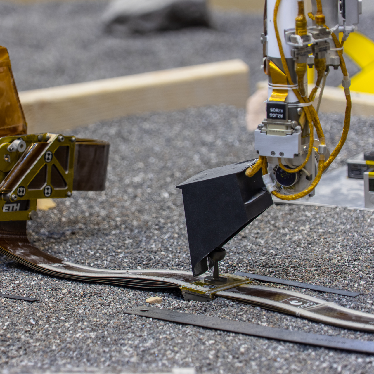
With the gripper now attached alongside the robotic arm during sol 50, the SEIS instrument’s tether operations could be continued. Remember that the goal was to widen the gap between the LSA’s two metal plates so as to avoid interfering vibrations travelling along the cable by moving it further away using the pinning mass.
To move the pinning mass, the robotic arm’s bucket was positioned around 5 cm from the mass. Four additional movements of 2 cm along the tether axis were used to bring the bucket closer to the pinning mass handle, begin resting on it then actually move it. The arm was then supposed to free the pinning mass so as to take images of the LSA (it not being possible to see both the pinning mass and the LSA properly at the same time with the IDC).
Theoretically, to avoid interfering vibrations, the two LSA plates had only to be separated by a very small gap (a few nanometres should be enough). However, as it was possible that the tether could slacken after a while (or after WTS deployment), the project engineers decided that a distance of 2 cm was necessary to finally validate deployment. On the other hand, they had to make sure that the LSA gap was not enough for the outside plate to touch the WTS skirt.
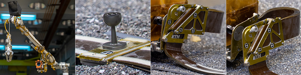 From left to right (1) InSight’s robotic arm with the bucket, gripper and IDC (2) the pinning mass on the tether connecting the SEIS seismometer to the InSight lander and (3 & 4) the LSA in “closed” position (with the metal plates touching) then “open” position (with a gap between the plates). The LSA makes the SEIS tether form a service loop to avoid interfering vibrations that can travel along it and interfere with seismic measurements (NASA/JPL-Caltech/IPGP/Philippe Labrot).
Two techniques could be used to check that the gap between the two LSA plates was wide enough. The first, most obvious, one was to take pictures with the IDC on the robotic arm. This option was only valid if the plates were at least 2 cm apart. Otherwise it was not possible from the images to see the Martian soil in the gap between the two plates.
The second technique was less obvious but proved extremely useful. It required using SEIS’s SP and VBB sensors to listen out for characteristic resonance. Depending on the gap between the two LSA plates, the seismometer measured series of vibrations at certain frequencies that could be used to precisely quantify the gap and see which distance was most advantageous. With the LSA “closed”, it acts like quite a rigid system that vibrates at fairly high frequencies. When it is “open”, however, it is less rigid so oscillates more freely in different directions and at lower frequencies. The idea was not to optimize the LSA gap depending on the frequencies of vibrations observed. This technique clearly confirmed, however, the separation of the two plates and correct functioning of the service loop.
 JPL’s ForeSight test bed was used to practise adjusting the pinning mass’s position using the robotic arm’s bucket, sol 48 (© NASA/JPL-Caltech/IPGP/Philippe Labrot).
Three-dimensional positioning in space being more difficult to gauge for the bucket than for the gripper, preliminary manoeuvres were carried out on sol 52 to determine the movements to programme so that the bucket would remain in contact with the pinning mass. The first attempt at adjusting the pinning mass was then scheduled for sol 54 (20 January 2019). However, an incident involving DSS-26, the 34-metre antenna at the Goldstone Deep Space Communications Complex, meant that no commands could be sent to Mars and entailed postponing the first attempt to sol 56.
The images taken on sol 56 showed that although the robotic arm’s bucket was properly aligned with the tether, it only slightly touched the pinning mass handle, which was not enough to move it. This failure to widen the gap between the two LSA plates meant that they were still touching.
A second attempt was made on sol 59. This time, the bucket was lowered by an extra 7 mm, and the backward movement increased by 3 cm. Although the pinning mass was actually pulled, the LSA plates were still not wide enough apart (which is hardly surprising in the light of the cable’s rigidity). Despite what the pictures seem to show, the two plates had in fact been separated, but the gap at the top was still too narrow. At the bottom, the plates were about 2 cm apart: as the LSA plates are not perfectly parallel, the gap at the bottom is a little wider than at the top. Although this gap was not wide enough for the seismologists, the separation of the two plates was confirmed by the resonance measurements taken by SEIS’s seismic sensors.
A third attempt during sol 61 finally optimized the gap between the LSA plates, which was 2 cm at the top and 5 cm at the bottom. During all these operations on the tether, the levelling cradle inclinometers showed that SEIS hardly moved at all, thus indicating its excellent stability on the Martian surface.
Following the separation of the two LSA plates using a Frangibolt during sol 40, it took engineers over 20 sols in all to widen the gap sufficiently. The time taken for these surface operations may be explained by the fact that to successfully pull on the tether, the robotic arm had to perform two particularly complicated operations: stowing the gripper and adjusting the position of the pinning mass. The scientists used this period to collect many data from SEIS. The sensors were switched on for increasingly long periods of time, and the VBB pendulums were even switched to science mode (which was not originally planned before deployment of the WTS). The data proved to be of excellent quality.
Wind and dust storms: the need for a WTS
From a “weather” viewpoint, 2018 was an eventful year on Mars. First detected in late May in the Perseverance Valley region, a dust storm arose that became so large it ended up covering the whole planet in June 2018 (causing the unfortunate loss of communication with Opportunity, the US rover operating close to its origin). Although the storm weakened in September, the Martian atmosphere is still extremely dusty and the phenomenon remains a real threat. From sol 42 (8 January 2019), data from NASA’s Mars Reconnaissance Orbiter showed that another localized dust storm was forming in the Red Planet’s southern hemisphere.
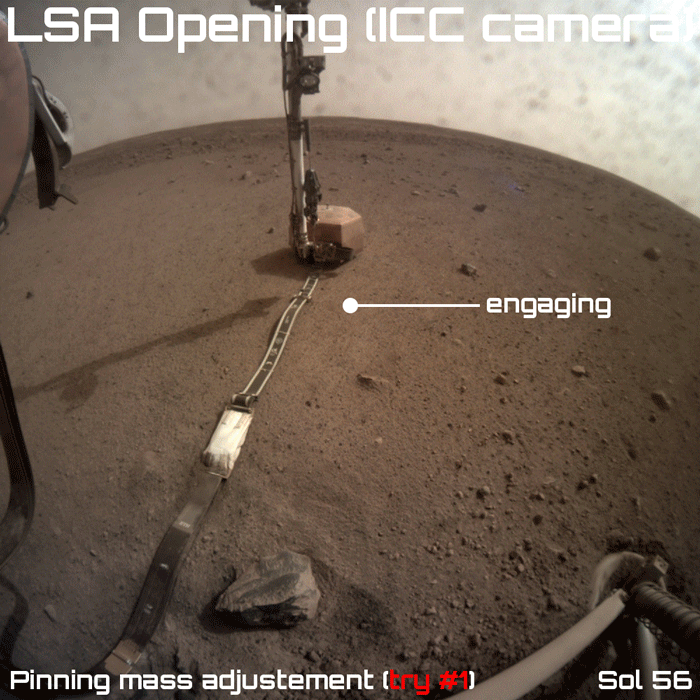 Animated sequence of images taken by the instrument context camera (ICC) showing attempts to adjust the position of the pinning mass attached to the SEIS tether on Mars (© NASA/JPL-Caltech/IPGP).InSight’s solar arrays were designed to be very efficient to counter the dimming effect of dust in the air. In nominal operation, they produce more daily power than any previous mission to Mars. Following this new dust storm, their power dropped by 20% over just three sols in succession. Although the situation has become stable once again, project engineers continue to keep a close eye on the power provided by InSight’s solar arrays.
Generally speaking, there is quite a lot of wind around the InSight landing site. The sound recordings provided by the SP sensors and the weather station’s auxiliary payload sensor system (APSS), which reflect the noise of wind billowing around the lander, are ample proof. The wind offers InSight a natural and quite efficient means of cleaning up, as it removes dust from all the surfaces where it can gather. This is obviously true for the solar arrays, but other instruments benefit too. The ICC lens, for example, was only partially protected from the dust raised by the blast of the retrorockets during landing in November 2018. The pictures taken by this camera clearly reveal that over time, the wind removes the particles stuck to the lens because the images become clearer as times goes by.
From a seismological point of view, however, wind is a major source of noise, and its effects need to be mitigated. This is why it is vital to place the WTS over the sensitive SEIS instrument to isolate it from the turbulent Martian environment.
In the third and last part of this series of articles on the deployment of the first seismometer to touch the Martian soil, we shall focus on deployment of the wind and thermal shield, WTS. For this step, almost as critical as deployment of the seismometer itself, the project engineers had to use the gripper again, this time to position it over the WTS and grab its handle, remove the WTS from the lander deck by activating a Frangibolt, then finally lift the shield off the lander and carefully place it over the seismometer. These operations constituted a single, continuous sequence.
Only with the WTS in position could the scientific observation campaign really begin. Protected by the WTS, the SEIS instrument’s seismic sensors will finally be kept on both day and night without worrying about temperatures becoming too extreme. At the time of writing, SEIS is switched off for the coldest 10 hours of the night. Protected from the particularly turbulent Martian environment, the pendulums will finally be in a position to record the Red Planet’s slightest quakes.
 JPL engineers Pranay Mishra (left) and Marleen Sundgaard (right) monitor a test on the ForeSight test bench to reposition the SEIS tether’s pinning mass using the bucket of the robotic arm. The goal is to pull on the SEIS tether to increase the gap between the two metal plates of the LSA service loop in order to stop unwanted vibrations travelling along the cable (© NASA/JPL-Caltech/IPGP/Philippe Labrot).