Reproducing Mars on Earth
InSight instrument deployment area replicated on Earth
Shortly after landing on 26 November 2018, the InSight lander began detailed mapping of the few square metres of terrain southward and just in front of the robotic IDA used to deploy its two main instruments. Using the instrument deployment camera (IDC) on the robotic IDA, the lander methodically swept the sector where the SEIS seismometer and the HP3 heat flow sensor were going to be set down, downlinking numerous data to project engineers and geologists.
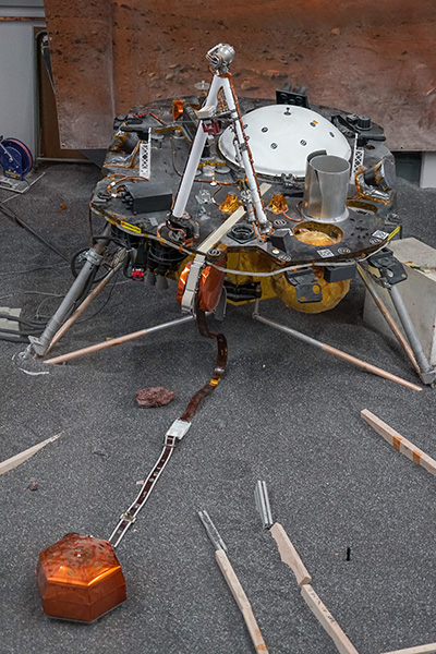 InSight’s twin, “ForeSight”, on the JPL test bed with the SEIS seismometer deployed on the ground during sol 18. The deployment area was divided into three. The small black peg to the right shows the intended position of the HP3 heat flow sensor (© NASA/JPL-Caltech/IPGP/Philippe Labrot).
Input into various visualization software programs, the information collected was used to build an extremely accurate digital terrain model, reproducing the finest details of the Martian surface. The smallest stone was identified and numbered, slopes measured and roughness determined so as to choose the best possible site for the SEIS seismometer’s deployment.
The computer study of the deployment area was just one part of the work, however. At the Jet Propulsion Laboratory (JPL) in California, a team of engineers had set up a whole test bed to reconstitute on Earth the Martian environment on Elysium Planitia. A full-scale model of InSight known as “ForeSight”, equipped with the deployment system (robotic IDA), the ICC and IDC technical cameras , etc.) dominates an area in which a 10-centimetre layer of mineral material (crushed garnet) has been poured to simulate the Martian regolith.
As soon as the Martian landing site had been fully characterized, engineers got to work making a sandpit replica. To reproduce the lander’s angle of inclination (with the deck leaning about 4° forwards), one of its legs had to be raised slightly. Various more or less sophisticated techniques were then used to place the biggest stones (over 2 cm in diameter) where they should be and model the surface.
The deployment area was divided up into three parts using lengths of wood. The sector just in front of the robotic arm was dedicated to the SEIS instrument and its wind and thermal shield (WTS). A smaller part towards the right was intended for the HP3 sensor. The two areas were separated by a path enabling the project engineers to walk around the deployment areas and reach the ForeSight model.
Although engineers sometimes used a simple tape measure when marking distances, they also used the Vicon motion capture system very popular in the film and video game industries. Sensors on tripods all around the sandpit provided very detailed information on the 3D position of small reflective spheres that the engineers placed on the instruments or rocks when needed.
The InSight instrument deployment team also used even more cutting-edge technology. To sculpt the terrain so it corresponds exactly to that on Mars, the engineers put on their Microsoft HoloLens augmented-reality headsets. Holographic information was then projected onto the sandpit so they saw a 3D model of the lander superimposed on the actual ForeSight lander.
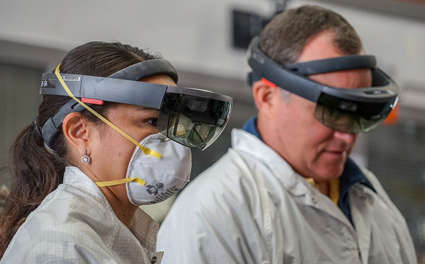 Marleen Sundgaard (systems engineer responsible for the InSight test bed at JPL) and Tom Hoffman (InSight project manager at JPL) monitoring operations to reconstruct on the ForeSight test bed the deployment site for SEIS and HP3 (sol15, © NASA/JPL-Caltech/IPGP/Philippe Labrot).
Controlled both by hand gestures and vocal commands, these augmented-reality headsets reveal information too subtle to be seen properly with the naked eye. Slopes, dips and bumps can be clearly seen through the headset as coloured surfaces or multicoloured grids. By projecting a digital terrain model onto the sandpit, the engineers saw where they had to remove or add material or even flatten areas.
Once ForeSight’s Martian rock garden was perfectly modelled, they could download to the lander the command sequences to be tested before being sent up to Mars. To simulate Martian gravity, the robotic arm (IDA) was attached to a hoist so as to be artificially supported. The whole deployment sequence was then run, usually in front of a crowd of mission engineers and scientists invited to watch the event through a large window overlooking the test bed.
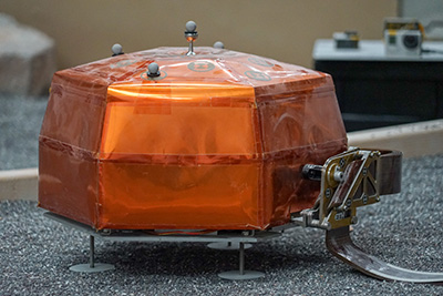 The test bed SEIS seismometer including the Vicon reflective spheres (sol 18). Note the small sphere on the handle (© NASA/JPL-Caltech/IPGP/Philippe Labrot).The deployment sequence is both fascinating and impressive to watch. By slow movements—sometimes graceful, sometimes jerky—the robotic arm IDA begins by positioning its gripper over the SEIS instrument. The gripper’s claws then close over the small semi-spherical handle on top of the hexagonal copper-coloured RWEB that houses the sensors.
Once SEIS has been grabbed, the arm raises the instrument vertically before moving backwards and rotating 180°. The arm is then extended as far as it can go while lowering the instrument gently onto the Martian surface. The gripper then opens to free the seismometer, which remains connected to the lander by a sophisticated tether composed of five rigid and independent ribbon cables.
Once validated, the sequence of commands tested on Earth in conditions as close to reality as possible will be uplinked to the InSight lander on Mars, which will then run the fully-automated sequence.
Pour aller plus loin :
-
Portrait of Marleen Martinez Sundgaard, manager of the ForeSight test bed.
-
Portrait of Ashitey Trebi-Ollennu, in charge of InSight’s robotic IDA.