")

Deployment of the instruments
The SEIS seismometer and the HP3 penetrator must be placed on the ground
Once safe and sound on the dreary, dusty plain known as Elysium Planitia, the InSight probe will initiate a crucial stage in the mission: the placing of the two main instruments, SEIS and HP3, carefully on the Martian soil.
Placement zone
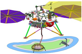 A deployment zone for SEIS and HP3 of around 3m² (© NASA).The limited movement of the robotic Instrument Deployment Arm (IDA) means that the seismometer and HP3 penetrator must be positioned in front of the lander, within a crescent-shaped area approximately 3 m long and 2 m wide. The area available for the HP3 instrument (3.4 m²) is bigger than that allocated to the SEIS instrument (3.1 m²).
The area where the instruments are to be placed will be photographed in great detail by the InSight lander’s technical cameras. Attached to the IDA, the Instrument Deployment Camera (IDC) moves so as to take stereo-pair images overlapping by about 80% and will cover the whole surface. The first set of eight images is taken with the IDA above the lander deck, to ensure that the second shot, taken one metre above the ground, is reliable. Following that, 24 stereo-pair images will be recorded for input into a Digital Elevation Model (DEM) with a resolution of around one centimetre.
All the phases of the instrument setting-down process will also be photographed: pre-positioning the gripper then engagement, raising then lowering the instrument onto the ground, freeing the load, etc.
Sandpit
The whole deployment process will be simulated on Earth in a giant sandpit within a huge hangar before being carried out on Mars. A working model of the lander fitted with cameras and a robotic arm similar in all respects to the real probe is to be set up in an enclosure. The mock-up will also include dummy instruments identical in mass and volume to those sent to Mars.
Using the images from the technical cameras and supported by a digital elevation model (a computerized 3D model of the landing site), a terrain modelling the Martian surface down to the least detail can be created. The sandpit will be filled with a reddish material simulating the crushed, powdery soil that specialists call the regolith. Rocks of various shapes and sizes will then be added for realism, because unlike a Japanese garden, the objective is not aesthetic, but rather to stick as closely as possible to the ground truth!
Instrument deployment
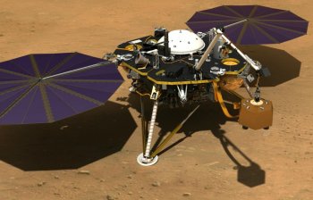 Deployment of the SEIS seismometer by the InSight probe’s IDA (© NASA).
Once the few square metres of the landing site on Elysium Planitia have been duplicated on Earth, mission engineers will begin a series of tests that will lead to the development of a set of commands for the first step of the deployment process.
Once validated, these commands will be sent to Mars for the InSight probe to execute. This process will be repeated step by step until both instruments are correctly deployed on the Martian soil.
The team in charge of instrument deployment will obviously take their time. A detailed schedule, partly dictated by the telecommunications bandwidth allocated, has already been established. After each step of the deployment process, checks crucial to the go-ahead for further operations will be made. The engineers involved will have a comfortable margin at each key point and at the end of the deployment process in order to respond to the unforeseen situations inevitable with this kind of activity.
The critical deployment phase is split into six parts and could take up to two months after landing (with a margin of 20 sols). During this time, the teams will be constantly on hand, unlike during the scientific measurement phase, when the probe will be operating practically on its own. The operations schedule is given below:
-
Sols 0 - 5: initialization of the lander and preparation for instrument deployment.
-
Sols 6 - 18 : characterization by the cameras of the room available for positioning the instruments and selection of the most advantageous potential sites for deployment.
-
Sol 7 (science) : initiation of RISE data acquisition (geodesy).
-
Sols 19 - 31 : deployment of the SEIS seismometer (see details below). Start of measurements in engineering mode.
-
Sols 32 - 43 : deployment of the seismometer’s Wind and Thermal Shield (WTS). Start of SEIS scientific measurements (monitoring) from sol 40.
-
Sols 44 - 58 : deployment of the HP3 suite. Its mission accomplished, the robotic IDA returns to a stowed position on the lander.
-
Sols 59 - 69 : start of drilling operations with the HP3 mole.
Deployment of SEIS
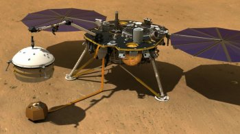 The InSight probe’s robotic arm carefully places the WTS over SEIS (© NASA).
The SEIS seismometer’s deployment is the top priority. The rigidity of the communications and power supply cable will prevent the instrument being set down in certain parts of the deployment area.
In the event of an incident, it should be possible to lift the seismometer again and set it down elsewhere, but certain movements (such as to the rear) are forbidden due to cable constraints.
Once the seismometer is resting firmly on its levelling system tripod on the Martian soil, it must be covered by the Wind and Thermal Shield (WTS), which amounts to a large protective cover. The deployment engineers have to ensure that they leave a gap of at least 6 cm between the outside of the seismometer and the inside of the WTS.
Next comes HP3, designed to measure heat flow. No doubt to thank it for waiting so long, the HP3 mole will be allowed to start burrowing down into the Martian soil just after being set down on the surface.
Commissioning the SEIS seismometer
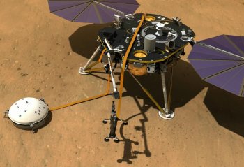 The InSight probe’s robotic IDA setting down HP3 (© NASA).
The SEIS instrument will be commissioned through a series of successive steps described below.
First, SEIS will be placed on the ground with the gripper still attached. Preliminary measurements will then be taken in this configuration. If the position is unsuitable, the seismometer may be easily moved without having to try to grab the instrument’s carrying handle again with the gripper on the robotic arm, always a tricky manoeuvre.
Deploying a seismometer on the surface of another planet is a real challenge. It is absolutely crucial for SEIS to be set down on a surface inclined at less than 15°. The surface must also be flat, without any rocks, and able to support the seismometer and its heavy protective shield (WTS). Finally, the seismic coupling—in other words, the quality of contact between the soil and the seismometer’s legs—must be no less than excellent.
Up to now, the only instruments set down directly on the surface of a celestial body other than Earth—the Moon—have been placed there with the invaluable help of humans. This is the first time ever that a robot will be used. Even the Martian rovers have never carried out such an operation, even though they have sometimes moved sensors on robotic arms closer to rocks or the ground.
Once the SEIS seismometer is on the ground, the levelling system is activated in order to align the instrument horizontally to within 0.3°. Inside the evacuated sphere, the VBB pendulums are then recentred using the balancing device. For the launch, the pendulum recentering motor is stowed away, and the mobile mass is kept up near the end stop. Once on Mars, the mass is moved to precisely centre the pendulums and find the right balance between Martian gravity and the force used by the spring to bring the pendulums back into their central position. Once centred, they can be calibrated.
 InSight probe with the SEIS and HP3 instruments on the ground (© NASA).To check the quality of seismic coupling and confirm the choice of site, measurements will be taken in engineering mode for one Martian day (i.e. a sol). Engineering mode is quite resistant to temperature fluctuations (which are not corrected at this stage), but it does not offer high enough performance for scientific measurements. In this mode, the seismometer cannot be saturated, i.e. be submerged by the amplitude of signals recorded, which is an advantage.
If the data gathered during this first day are not satisfactory, the seismometer (still attached to the gripper) will be moved. If all is well, the IDA releases the instrument and proceeds to cover it with its protective shield, the WTS.
In this configuration, the Thermal Compensation Device Mechanism (TCDM) on each pendulum can then be activated. In its launch configuration, the TCDM is aligned vertically, a position in which it cannot affect the pendulum. Now that the seismometer is on Mars, it has to be positioned in order to reduce as much as possible the effects of variations in temperature.
The variations in temperature throughout a day will be observed in engineering mode, with the TCDM vertical (0°). The resulting seismic signal graph is a sine wave.
The following day, the TCDM is turned by 90°, its most efficient position. The aim is to efficiently reduce the effects of temperature variations by a factor of 10, for example. Contrary to what one might think, the TCDM’s effectiveness does not depend on the amplitude of variations, but the mean temperature. It is nonetheless possible that the TCDM dampens the movement too much.
Over the next few days, the TCDM may be rotated to a given angle to optimize its operation with respect to the observations of the previous days.
The seismometer will remain in engineering mode until the TCDM has been finally adjusted.It will then be switched to science mode, which is not compatible with strong temperature variations (now compensated by the TCDM), and less robust than engineering mode as there is a risk of the sensors being saturated in certain conditions. However, its measurement performance in this mode matches that required by the international scientific community.