The Instrument Deployment Arm (IDA)
A two-metre-long robotic arm
InSight has a sophisticated robotic arm designed for a single purpose: to deploy with the greatest precision and safety possible the mission's two main instruments, namely the SEIS seismometer and the HP3 heat flow sensor.
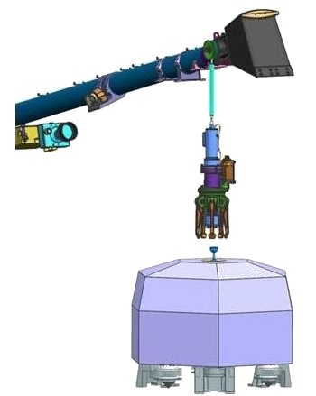
 3D graphic representation of the IDA in the process of lifting the SEIS seismometer (© NASA).
Contrary to what you might think, even once firmly on its three legs, the landing phase is still not over for InSight.
Its two main instruments— SEIS and HP3 —are still about one metre from the Martian surface, with which they absolutely must make contact before they can begin to take any measurements.
With the aid of two cameras, project engineers need to choose a landing site for these two instruments before setting them down using the robotic arm.
InSight’s Instrument Deployment Arm (IDA) is exactly the same as the one built for the Mars Surveyor mission in 2001, subsequently cancelled after the unexplained disappearance of the Mars Polar Lander above Mars' South Pole in December 1999. This arm was itself derived from the one on the Mars Polar Lander. The robotic arm on the 2001 Mars Surveyor had been designed not to place an instrument on the surface of Mars, but the Marie Curie rover, an exact copy of the small Sojourner vehicle from the Pathfinder probe that had trundled over the Red Planet in 1997.
Stored in a container for over a decade awaiting eventual re-use, the 2001 Mars Surveyor robotic arm was finally awoken from its long slumber for the InSight mission.
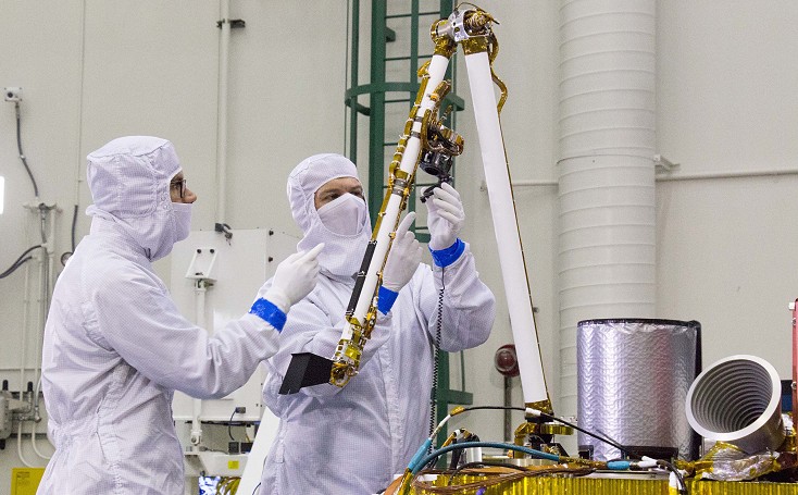
 Testing the IDA. An engineer is handling the protective cover of the instrument deployment camera (IDC) (© NASA/JPL-Caltech/Lockheed Martin).
Since there have been many technical advances since it was first designed, refurbishing the IDA to as-new condition and re-certifying it for spaceflight provided Jet Propulsion Laboratory engineers with some interesting and unusual challenges. Once out of its container, the arm was scrupulously checked and tested by the engineers before being almost completely disassembled in order to replace certain parts before reassembly. The arm was judged to be in generally excellent condition despite its 13 years in storage.
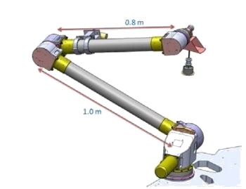
 Dimensions in metres of the IDA flown on the InSight probe (©NASA).
Attached to the lander’s deck, the IDA is structurally identical to a human arm: it comprises an upper limb linked to a forearm via a motorized elbow. The forearm ends in a mobile wrist to which an ingenious gripper is attached. The assembly has four degrees of freedom, each with a motor: two for the joint between the upper limb and the lander deck (the shoulder), one for the elbow, and one for the wrist.
The two tubular segments of the arm are made of a carbon fibre composite material combined with aluminium and titanium. The upper limb is 1 m long, as against 80 cm for the forearm. Extended to its limit, the arm can reach a zone 1.9 m from the lander.
The motors used have a long heritage in the history of Martian exploration, being used in particular for the Pathfinder mission on the little Sojourner rover (1997), then on the Spirit and Opportunity rovers (2004), and finally on the Phoenix polar probe (2008). A noteworthy feature of the motors is that they contain heater elements to withstand the rigours of the Martian climate.
The IDA on the InSight probe has no problem lifting the SEIS seismometer (29 kg), the wind and thermal shield (WTS, 9,5 kg) and the HP3 penetrator (3 kg). Each device to be placed on the ground is fitted with a "handle" consisting of a rigid rod terminating in a sphere. This is designed so that it can be grasped as easily as possible by the gripper attached to the IDA.
A five-claw gripper
 Detail of the gripper on InSight's robotic arm (© NASA).
The gripper is attached to the end of the robotic arm's forearm via a 20-cm-long umbilical.
JPL engineers initially envisaged using a magnetic gripper. The magnetic force was provided by a rare earth permanent magnet (neodymium iron boron), and the loads to be grasped were fitted with a magnetic puck.
Once near the objects to be placed on the ground, the gripper would be aligned automatically with the metal pucks attached to the objects. To make the set-down process more secure, a backup electromagnetic system was on hand to counteract the magnetic field, thereby releasing the load being transported.
Separating the gripper from its load would necessarily require an electric current to be passed. Hence there was no chance that the arm would inadvertently release its precious cargo if there were a sudden electrical failure during this deployment process. However, for reasons of reliability, the magnetic gripper was later replaced by a more conventional device, a five-digit pincer.
This question of reliability is linked to one of the features of the Martian environment, i.e. the constant presence of dust on every surface. With much of it containing oxides of iron, this dust is by its very nature attracted to magnetic surfaces. Since it would be impossible to keep the gripper clean on Mars, the risks created by dust-related interference forced the engineers to abandon their initial solution in favour of a more conventional—and more reliable—gripper.
Untroubled by the Martian environment, the current mechanical gripper cannot actually release its load by itself. The command to separate can only come from the Mission Control Centre on Earth, thus offering protection against any unintended release of the instruments by the arm.
Besides the gripper, InSight's robotic arm also has a bucket with a capacity of roughly 500 g of soil. However, this bucket is not intended for massive excavation works; its main role is to prepare the ground as well as possible before setting the instruments down. It allows engineers to shift a stone that is in the way, flatten a little mound in an otherwise optimal deployment sector, or simply check the nature of the ground.
Last updated : 2 february 2018


