")

Very Broad Band (VBB) pendulums
A very complex yet modular mechanism developed by the Institut de Physique du Globe, Paris
-
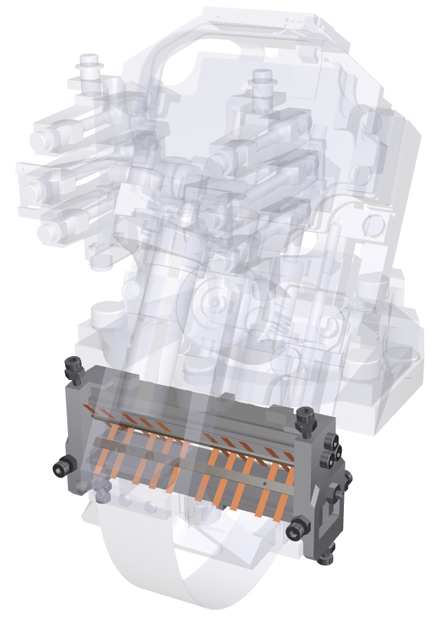
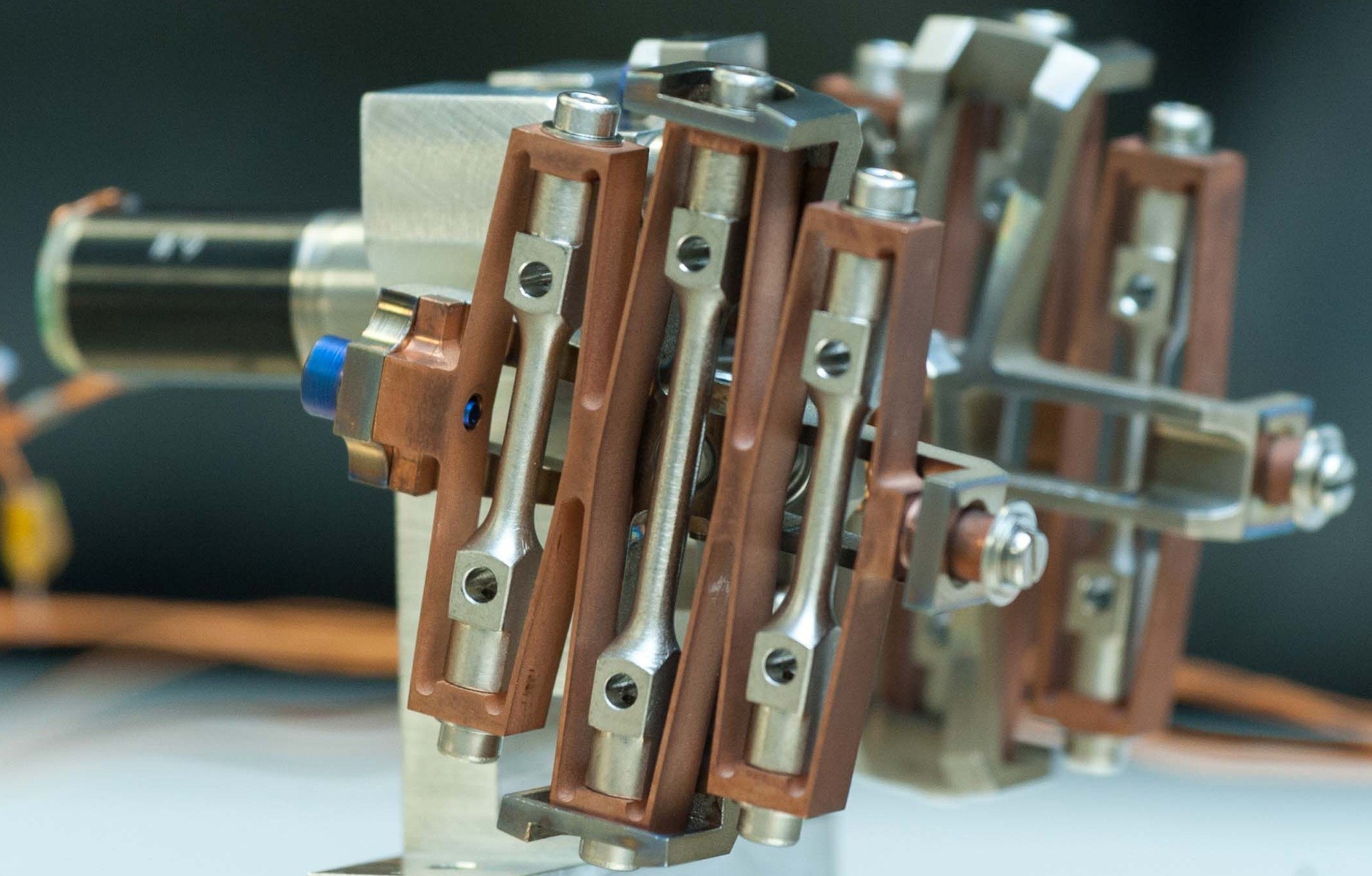
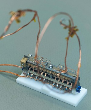 The lamellar pivot of a pendulum. The small copper lamellae bend to allow the moving part of the pendulum to be displaced frictionlessly by a tiny amount with respect to the fixed part, (© Hervé Piraud / IPGP / SODERN)
The pivot
All seismometers comprise a moving part and a fixed part. When the ground moves, the vibrations are transmitted to the mobile part, which then follows the displacements transmitted by the ground and moves with respect to the fixed part. The two parts, fixed and mobile, must therefore be able to pivot freely with respect to one another. The pivot's role is to provide this articulation, which must be friction-free.
For a given pendulum, the two parts can pivot only in a single direction, or axis. This explains why a modern seismometer such as SEIS has three pendulums, one for each spatial direction.
Like all the other SEIS pendulum components, the pivot is a marvel of technology, but also a complex and fragile mechanism, 5,2 cm long by 1,8 cm high. Made mostly of titanium, it comprises an upper beam connected to the fixed part, and a lower beam fixed to the mobile part via the spring and the pivot itself.
The upper beam (which cannot move) and the lower beam (which can) are connected to each other by the pivot's 20 small flexible lamellae. Made of a beryllium copper alloy, these very fragile and delicate lamellae (their thickness is only of 50 microns) flex to allow the mobile part to move with respect to the fixed part. Together, they form a virtual axis of rotation.
It is not hard to imagine that in such a mechanism the degree of freedom of the moving part with respect to the fixed part is necessarily very limited, which is indeed the case. At most, the moving part can pivot just 50 microns! An ingenious adjustable end stop has been designed to avoid exceeding this value. This mechanical system avoids any risk of distorting or breaking the lamellae.
Each pivot has unique characteristics. Of all the pivots made, only those that demonstrated optimal functionality were selected for the Mars seismometer pendulums. The pivots were also selected with regard to the properties of the springs, which are also unique. The SEIS project engineers therefore had to form pivot-spring pairs that were as well matched as possible.
During the design and construction of the pivot, the technical teams were faced with several technical challenges, requiring a "tiger team" of experts and specialists brought together with the sole objective of understanding and resolving the technical problems encountered.
On the qualification models, for instance, a very slight flexure (buckling) of one of the beams when exposed to cold caused the pendulum’s natural frequency (i.e. the frequency at which the pendulum is most sensitive) to shift. The greater the drop in temperature, the greater the shift in frequency, which ended up causing an instability in the pendulum that in turn prevented any measurements from being taken.
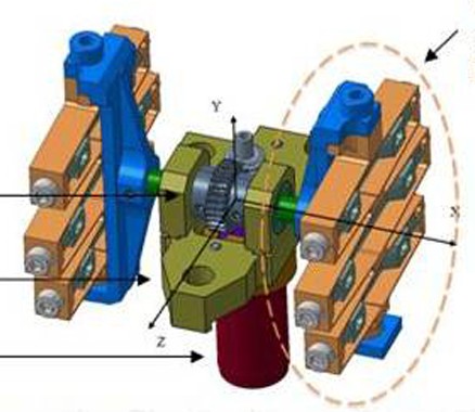
 Location of the pivot on the VBB pendulum (© IPGP/David Ducros).
This simple example shows the extent to which the pendulums of the SEIS Martian seismometer are integrated systems. If just one of the components drifts off optimal operation, the seismometer’s sensitivity and performance suddenly deteriorate or collapse completely, thereby preventing the instrument from meeting the scientific requirements for which it was designed.
The two parts of each pendulum can only pivot in one direction, or axis. This explains why most modern seismometers such as SEIS have three pendulums, one for each spatial dimension.
Last updated: 17 august 2017
-
 The lamellar spring of a pendulum. Note the small mass at the bottom centre used to test the pendulum under terrestrial conditions. Also visible at the top is the equilibrating motor, which resembles a small battery. (© Hervé Piraud / IPGP / SODERN)
The spring
The spring is a fundamental element of the SEIS seismometer, since it is what links the mobile part of the pendulum to the fixed part, and which therefore allows the first part to be displaced relative to the second. It is this spring that allows the pendulum to be in equilibrium with gravity. The restoring force that it continuously exerts brings the mobile mass back to its initial position after each vibration, and prevents it from irreversibly tipping over to one side or the other from its axis of rotation.
Each pendulum has a flat spring 12 cm long, 1,5 cm wide, and just 0,12 mm thick.
The springs are manufactured from a rather special material known as THERMELAST®. A special casting for all the InSight VBB sensor springs was ordered from the manufacturer just for this occasion. The considerable advantage of this magnetic alloy of iron and nickel in Martian conditions is its insensitivity to temperature variations, since it stores thermal strain energy in magnetic form.
In contrast to ordinary springs, which would expand or contract, the springs in the InSight pendulums remain insensitive to the drastic temperature contrasts that characterize the weather on the Red Planet. The downside is that the springs are sensitive to magnetic fields, a constraint that should not pose any problems on Mars, but which has nevertheless required the inclusion of a three-axis magnetometer to be able to correct the seismic signals for possible magnetic fluctuations.
Each spring has an absolutely unique identity, expressed through its physical characteristics. All the springs produced are tested individually, and only the best are kept. Given the very strong dependencies between the springs and other pendulum components such as the pivots or the exact mass of the mobile part and its inclination, all the components need to be matched together.
 Location of the spring on the VBB pendulum (© IPGP/David Ducros).
Project engineers therefore carried out a series of measurements to determine the springs' essential parameters, such as stiffness. Independent tests were also carried out on the pivots. A theoretical analysis was then used to couple a given spring with the most suitable pivot. However, it was not possible to match pivot and spring on this theoretical basis alone. Concrete measurements were then made with a test pendulum, and the behaviour of the spring was extrapolated to the other available pendulums according to the data gathered.
This meticulous work is absolutely essential to produce pendulums of the highest possible performance, knowing that only the best will be chosen for space flight, and have the honour of being installed in the flight model leaving for Mars.
Last updated: 17 august 2017
-
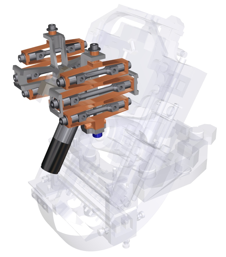
 The pendulum equilibrating motor resembles a small battery. It can fine-tune the mobile part of the pendulum with great precision before any measurements on Mars (© Hervé Piraud / IPGP / SODERN)
A precision mechanism for adjusting and centring the pendulums
Behind each pendulum is a tiny, but efficient, equilibrating mechanism. This comprises a small mass of roughly 50 g driven by a motor along a rail.
By sliding the mass along the rail towards or away from the pivot, it is possible to centre the moving part very precisely and zero it before starting a series of measurements. The motor-driven equilibrating system thus allows the equilibrium position of the pendulum’s mobile part to be adjusted with great precision.
The equilibrating mechanism is also very useful for adjusting the seismometer to the Martian gravity it will encounter at the landing site.
The gravity on planet Mars has been known for a very long time. At 3.71 m/s2, it is roughly a third of that on Earth. However, this is a mean value, and it can vary very subtly from region to region. For example, the Martian crust under the InSight landing site on Elysium Planitia only has to be slightly thicker for the gravity to be slightly greater than the mean value.
 Location of the equilibrating mechanism on the VBB pendulum (© IPGP/David Ducros).
Whatever the actual value of gravity that the InSight probe will discover after its arrival on Mars, the SEIS seismometer’s equilibrating devices will enable the pendulums to adapt as required.
With the passage of time, it is also probable that the mobile mass will drift mechanically due to fatigue in the pendulum. Once again, the equilibrating mechanism will tackle this problem.
Last updated: 25 October 2016
-
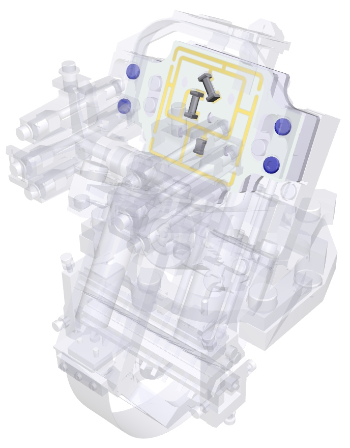
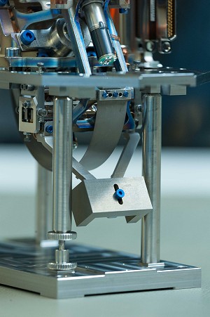
 The TCDM is an ingenious device that adjusts the pendulums with respect to the inevitable temperature variations on Mars (© Hervé Piraud / IPGP / SODERN).
TCDM, the mechanism supporting the thermal compensation device
The TCDM (Thermal Compensation Device Mechanism) is another "Martian" peculiarity of the SEIS seismometer. Clearly visible on the pendulum, this clever device allows the instrument to compensate for the variations in temperature that will affect its working environment, i.e. the vacuum conditions inside the titanium sphere. This passive mechanism adjusts the pendulum’s centre of gravity in response to temperature variations.
Despite all the care taken to thermally insulate the pendulums and the application of multiple protective barriers (low emissivity on the inside surface of the sphere, RWEB thermally protective cover, and the WTS), changes in temperature inside the sphere are inevitable. These will be +/- 5°C in winter and will exceed +/- 10°C in summer, with mean operating temperatures of -50°C in winter and -25°C in summer. These temperature variations need to be quantified and compensated for to allow the pendulums to operate at the performance level that scientists require.
Project engineers have therefore designed the TCDM—Thermal Compensation Device Mechanism—an ingenious mechanism attached to the moving part of the pendulum and comprising two small elements that look rather like miniature TV antennas or “ears” connected by a shaft via a central high-precision stepper motor.
These two antenna-shaped Thermal Compensation Devices (TCDs), positioned at each end of the TCDM shaft, are made of two different interleaved metals. Each metal has a different coefficient of expansion, so when the temperature changes, one barely expands or retracts at all, while the other expands or retracts significantly. It is this change in volume that subtly alters the pendulum's centre of gravity.
When the temperature rises inside the sphere, the TCDM will elongate in one direction rather like an accordion in an attempt to minimize the impact of the increasing temperature on the pendulum. Conversely, when the temperature falls, the TCDM will retract in order to neutralize the effects of the drop in temperature on the seismic sensor.
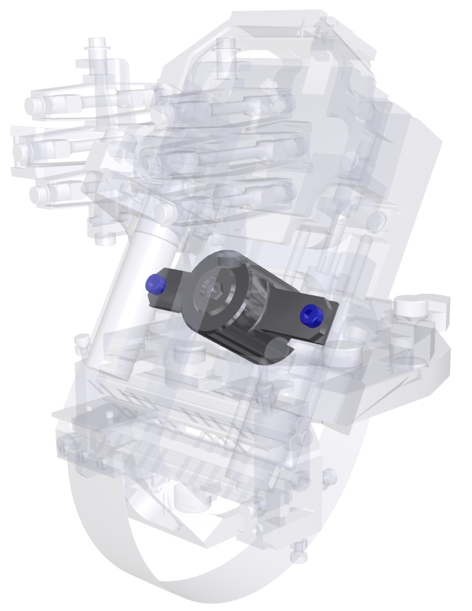
 Location of the TCDM on the VBB pendulum (© IPGP/David Ducros).
When the temperature rises inside the sphere, the TCDM will elongate in one direction rather like an accordion in an attempt to minimize the impact of the increasing temperature on the pendulum. Conversely, when the temperature falls, the TCDM will retract in order to neutralize the effects of the drop in temperature on the seismic sensor.
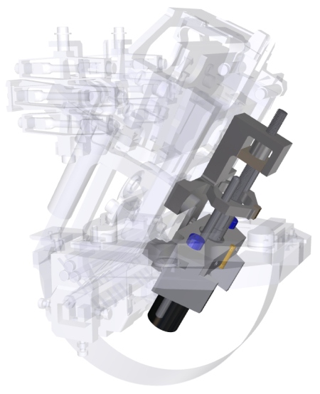
 Digital model of the TCDM, here in its vertical position (parallel to the field of gravity vector) (© IPGP)
Once on Mars, if the seismometer appears insensitive to Martian temperature variations, the TCDM will be positioned parallel to the field of gravity vector so as to have a weak influence. If, on the other hand, thermal sensitivity inside the sphere appears significant, the TCDM will be aligned perpendicular to the gravity vector so as to effectively counteract temperature fluctuations.
Digital model of the TCDM, here in its vertical position (parallel to the field of gravity vector) (© IPGP)
Once on Mars, if the seismometer appears insensitive to Martian temperature variations, the TCDM will be positioned parallel to the field of gravity vector so as to have a weak influence. If, on the other hand, thermal sensitivity inside the sphere appears significant, the TCDM will be aligned perpendicular to the gravity vector so as to effectively counteract temperature fluctuations.
Last updated: 25 October 2016
-
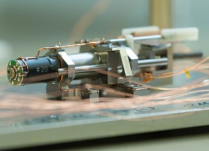
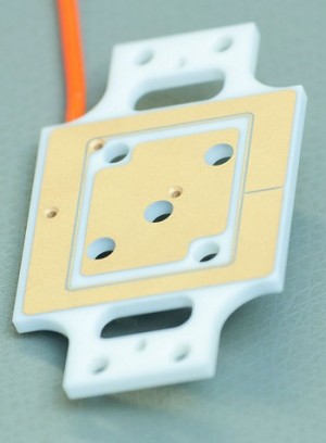 A ceramic electrode used in the DCS, which is capable of resolving ground displacements equivalent to a tenth of the radius of a hydrogen atom over periods in the order of one second (© Hervé Piraud / IPGP / SODERN)
The Differential Capacity Sensor (DCS) measures the displacements of the pendulum’s moving part
The differential capacity sensor (DCS) is vital to the SEIS pendulums. This is the sensor with the heavy responsibility of measuring the tiniest displacement of the moving part relative to the fixed frame. It must be as capable of registering very rapid movements of the ground as long-duration displacements that can last several thousand seconds.
The DCS is at the opposite end of the pivot. Here, the moving part of the SEIS pendulum can translate freely between two fixed zones in an aperture known as the airgap. The space between the mobile mass and the airgap is very small; it measures 150 microns though, as we shall see, just a fraction of this travel space will actually be used by the seismometer as it reacts to seismic events (the pivot itself can move through only 50 microns).
Both the airgap and the pendulum’s mobile mass carry electrodes etched onto small ceramic plates. The difference in electrical capacitance between the electrode of the mobile mass and the associated electrode mounted on the fixed part above and below the mass allows the motion of the moving part relative to the fixed part to be quantified very precisely. Capacitance is a unit expressed in farads that measures the quantity of electrical charge between two electrodes.
The differential capacity sensor is thus named because it measures pendulum movement by detecting the difference in electrical capacitance between a) the electrode pair comprising the upper fixed and moving electrodes, and b) the electrode pair comprising the lower fixed and moving electrodes.
To avoid a short-circuit, mechanical stops next to the DCS prevent the electrodes attached to the moving part from touching the electrodes on the airgap. The sensitivity of the DCS is around 3 volts per micron, i.e. each time the moving part is displaced by one micron (a millionth of a metre), the sensor generates a potential of 3 volts. The sensor noise, i.e. the signal recorded in the absence of any seismic events, is less than 10 microvolts, which corresponds to a displacement of less than 5 picometres (a thousand billionth of a metre) for seismic signals having a period of between 0.5 and 1 second.
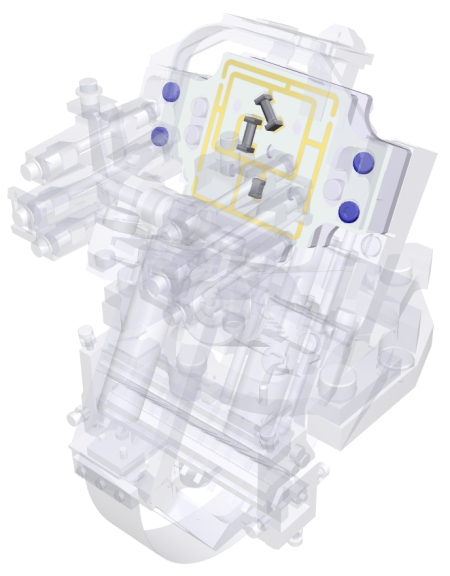 Location of the DCS on the VBB pendulum (© IPGP/David Ducros).
The accuracy of the DCS sensor is quite astounding. Thanks to this device, SEIS can measure displacements smaller than the distance between the electron and the nucleus of a hydrogen atom. This so-called Bohr radius (named after the Nobel physics laureate Niels Bohr) is roughly 0.5 ångströms, i.e. 50 picometres. In other words, SEIS is sensitive to ground movements expressible in terms of atomic distances and, for periods in the order of one second, can resolve ground displacements as small as one tenth of the radius of a hydrogen atom.
Last updated: 25 October 2016
-
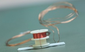 Feedback coil (© Hervé Piraud / IPGP / SODERN)
Feedback coils to optimize performance
As we have just seen, at each movement of the ground the displacement between the moving part of the pendulum relative to the fixed part is measured electrically via the DCS electrodes. However, contrary to what one might think, this measurement does not represent the signal coming out of the seismometer to be sent back to Earth and analysed later by scientists.
Like many terrestrial seismometers, SEIS is fitted with a feedback system that will optimize its operation for Martian conditions, significantly improving its performance.
The feedback device consists of three nested concentric coils fixed on the moving part and able to receive in the central hub a magnet which is itself bolted on the fixed part. Each coil comprises a small ceramic support around which a long length of very fine copper wire has been carefully wound.
There are three coils. The outer, largest coil is used for calibration purposes, and is able to inject a fluctuating motion that can then be checked against the seismometer reading. In other words, this coil imparts a virtual excitation of known amplitude to the moving part, allowing the pendulum to be adjusted.
The intermediate coil is designed to measure short-period seismic signals, whose oscillations occur over short intervals of time (less than 50 seconds). Its primary role is to dampen excessive jolts and pendulum resonance, and prevent the pendulum from banging against the protective stops.
Finally, the inner, smallest coil is designed, in contrast, to kick in for long-period seismic signals. Its main feature is that it can follow slow oscillations, despite the inevitable temperature variations that occur over the course of time between day and night.
Principle of operation
Whenever the mobile mass is displaced by vibration, the electric currents generated by the voltage across the DCS and conditioned by the sensor's electronics are sent to the two feedback coils on the moving part of the pendulum. Interacting with the magnetic field created by the magnets attached to the fixed parts, these currents create a restoring force that returns the displacement to zero. If this displacement is zero, the output voltage of the position sensor will also be zero. If the instrument were perfect, the moving part would never move, regardless of any external excitation.
 Location of the feedback device on the VBB pendulum (© IPGP/David Ducros).
The voltages generated by these currents continuously counterbalance any motions of the moving part that the seismometer might register, and constitute the seismic measurement. Initially expressed in volts, a transfer function then converts the signals into displacements of the Martian surface.
The servomechanism keeping it at equilibrium enhances the performance of the pendulum, in particular for long-period ground movements (whose oscillations can last tens or hundreds of seconds) that are of greatest importance to scientists.
Last updated: 25 October 2016