Temperature, impacts and vibration, vacuum, radiation and electromagnetic fields, everything has to be tested!
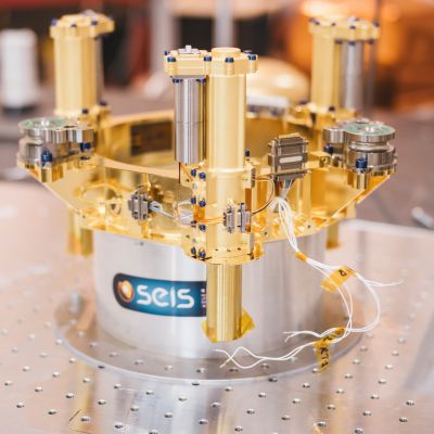
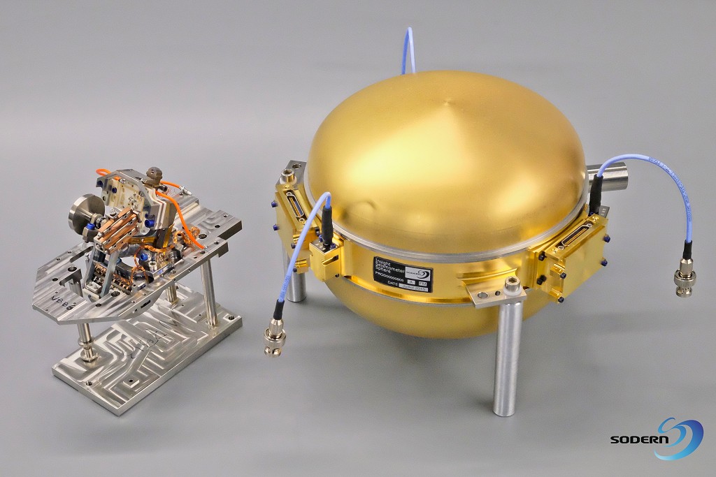
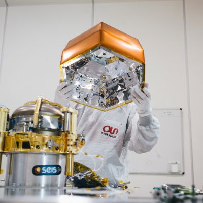
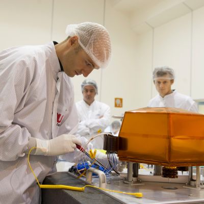
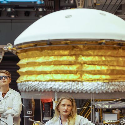
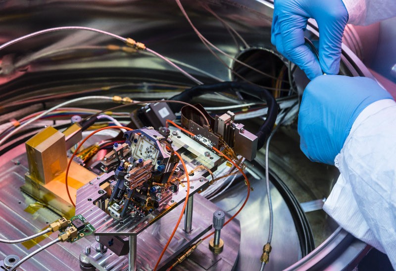
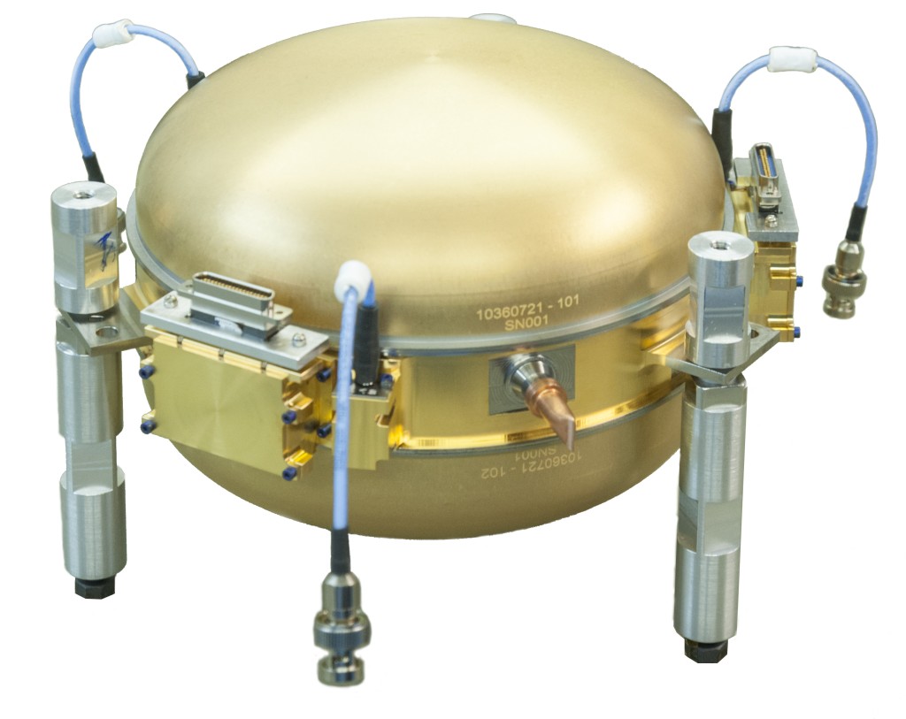
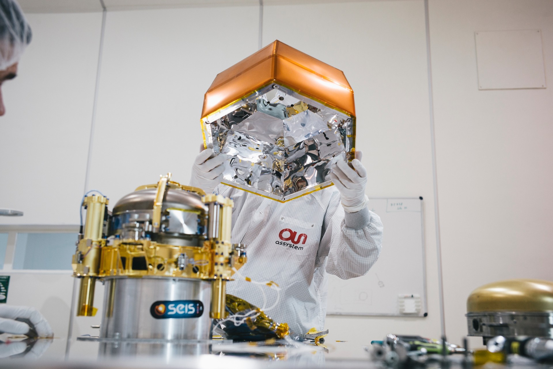
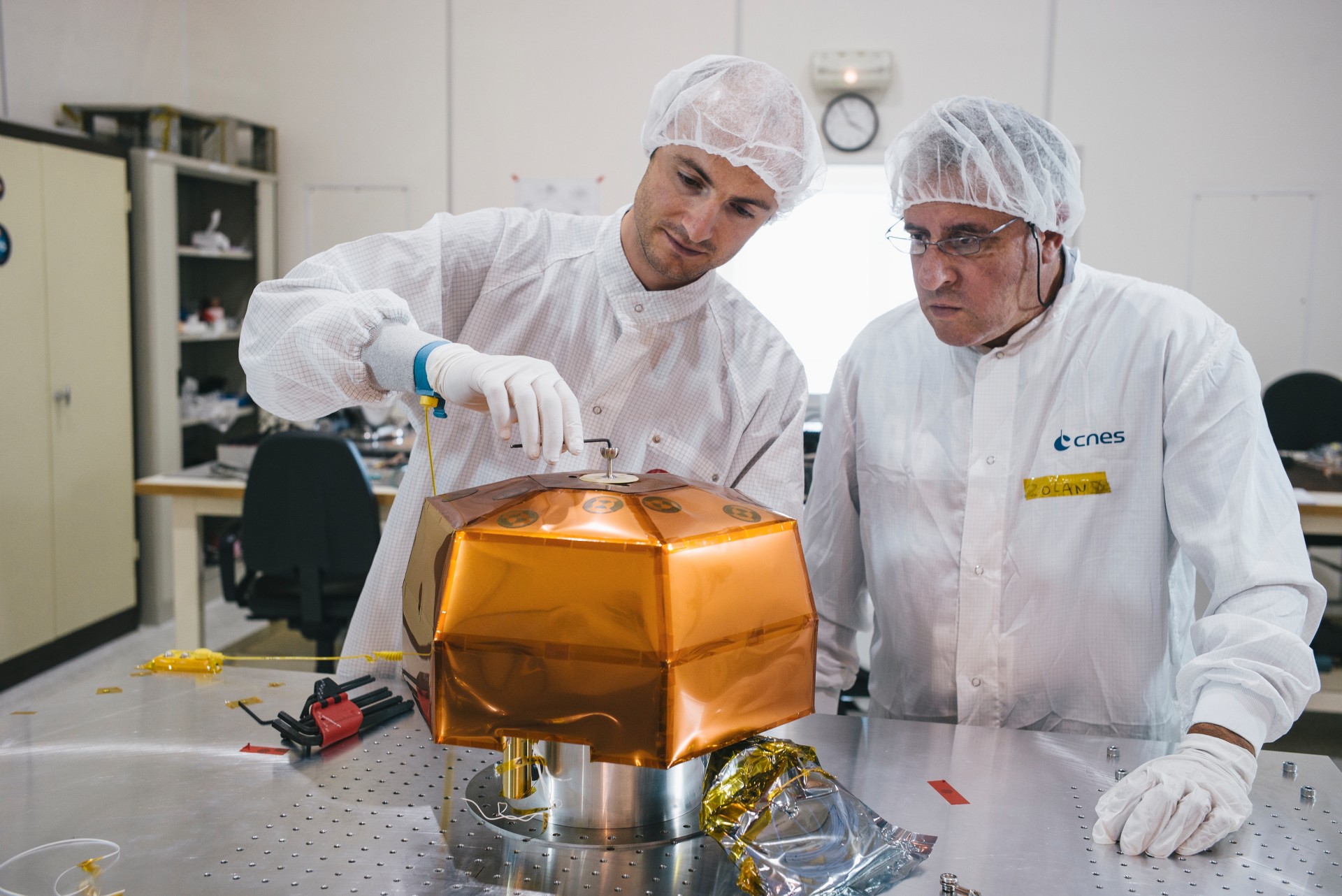
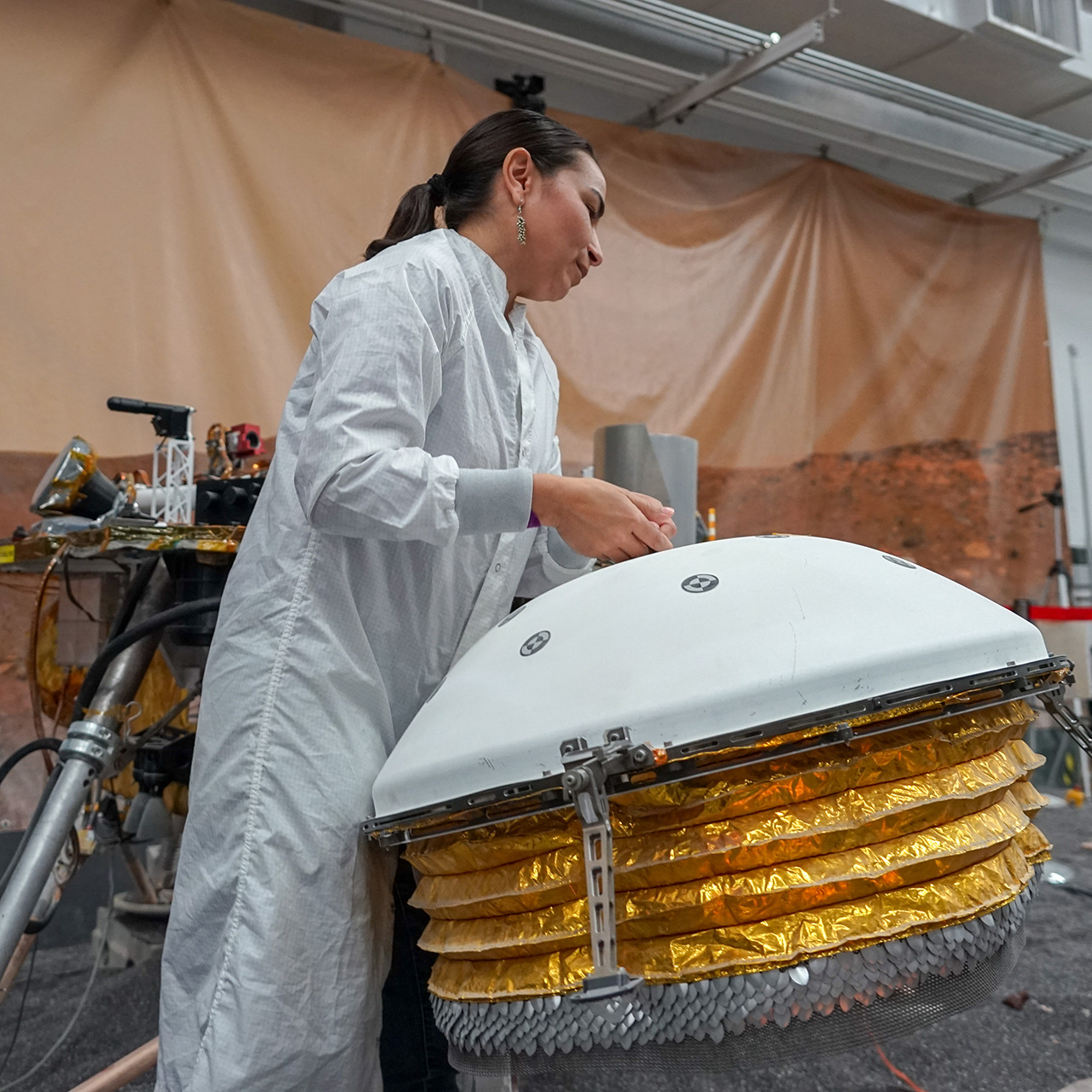
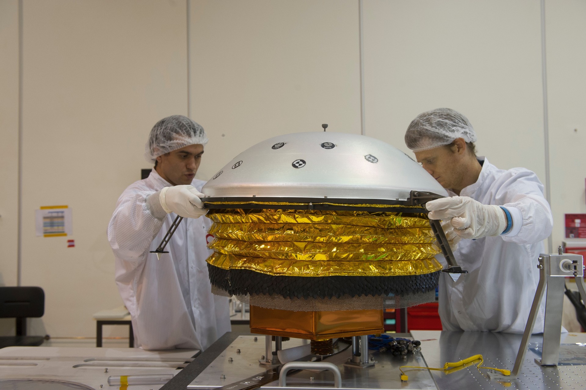
.") Inspection of the SEIS seismometer sphere (¬© Hervé Piraud/IPGP/SODERN/CNES).
Inspection of the SEIS seismometer sphere (¬© Hervé Piraud/IPGP/SODERN/CNES).
Testing is of absolutely vital importance in the space sector. On this depends the correct operation of an instrument in space, and hence the success of the mission.
Test models
The battery of tests starts right from the instrument’s design phase. The structural and thermal model (STM) is used to validate two key aspects of an instrument: its structural strength, and its behaviour under thermal stress.
Engineers then develop a functional qualification model (QM) on which an entire series of test is conducted, including electrical tests. If these are satisfactory as a whole, a flight model intended to be launched into space can then be built, at the same time as a spare that can be used in the event that the flight model develops a failure. Flight and spare models are, of course, tested in the same way as the qualification model.
The number of tests to which a space instrument is subjected is remarkable, and reflects the challenges encountered during its development. Generally speaking, tests are split into two major groups: functional tests and environmental tests.
Functional tests: does the instrument work properly?
.") Measuring instruments in the seismic cave at St-Maur (© Thierry Cantalupo/IPGP).
Measuring instruments in the seismic cave at St-Maur (© Thierry Cantalupo/IPGP).
The first thing to check is that the instrument functions properly in the environment in which it is intended to work.
Developing a Martian seismometer on Earth is not necessarily a great deal of fun. Not only does the instrument have to behave correctly on Earth but it also has to operate perfectly under Martian conditions, i.e. at glacial temperatures (down to 65°C below zero) and in an atmosphere that is mostly CO2.
The seismometer is therefore regularly put into gas-tight chambers that simulate the Martian atmosphere. However, some aspects are impossible to replicate, such as the Martian gravity, which is one third of terrestrial gravity.
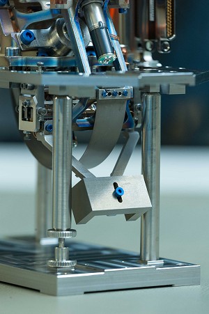
Project engineers have used some clever tricks to get as close as possible to reality. In the case of the SEIS seismometer, a small mass is added to the pendulum at the pivot, or it is inclined at a particular angle perpendicular to the inclined plane to obtain the same value of acceleration as that on Mars. However, this test is not without consequences, since terrestrial gravity nonetheless continues to exert its influence on the pendulum pivots.
Performance
The functional tests also encompass notions of performance. Not only must the instrument work, but it must also satisfy a minimum level of performance, e.g. in terms of sensitivity, so that it can meet the scientific problems for which it was designed. Many tests address the question of performance, and the data collected are analysed in minute detail to detect any unusual or disappointing behaviour.
Despite the efforts made to check the correct operation and performance level of the SEIS Martian seismometer, questions necessarily remain that will be identified and resolved only once SEIS is on Mars.
SEIS is an instrument designed to be ultra-sensitive since it is to be used on a planet that is seismically very quiet. Without the incessant noise from the pounding of ocean surf and the tumult of human activity, Mars is silent when compared to the Earth.
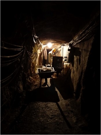
When powered up on Earth, the SEIS seismometer is immediately disturbed by a level of background noise that makes it impossible to determine its real characteristics with any exactitude. The engineers responsible for its design have tried placing the prototypes in environments cut off from the world, such as at the bottom of an abandoned mineshaft deep in the Black Forest, but in vain. Even down there the Earth is too noisy for periods of less than 20 seconds, and only a comparison between the signals recorded simultaneously both by SEIS and terrestrial seismometers was able to reveal the instrument’s own noise.
Environmental tests: impacts and vibration
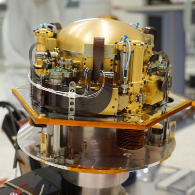
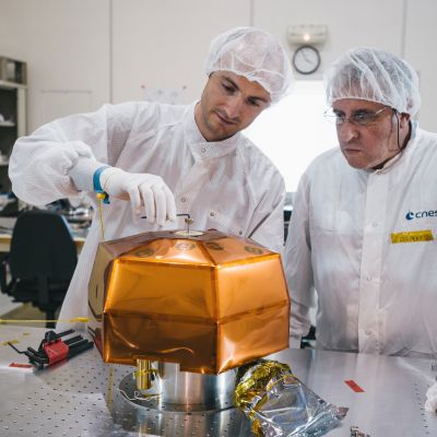
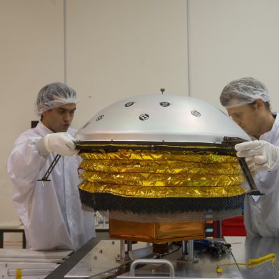
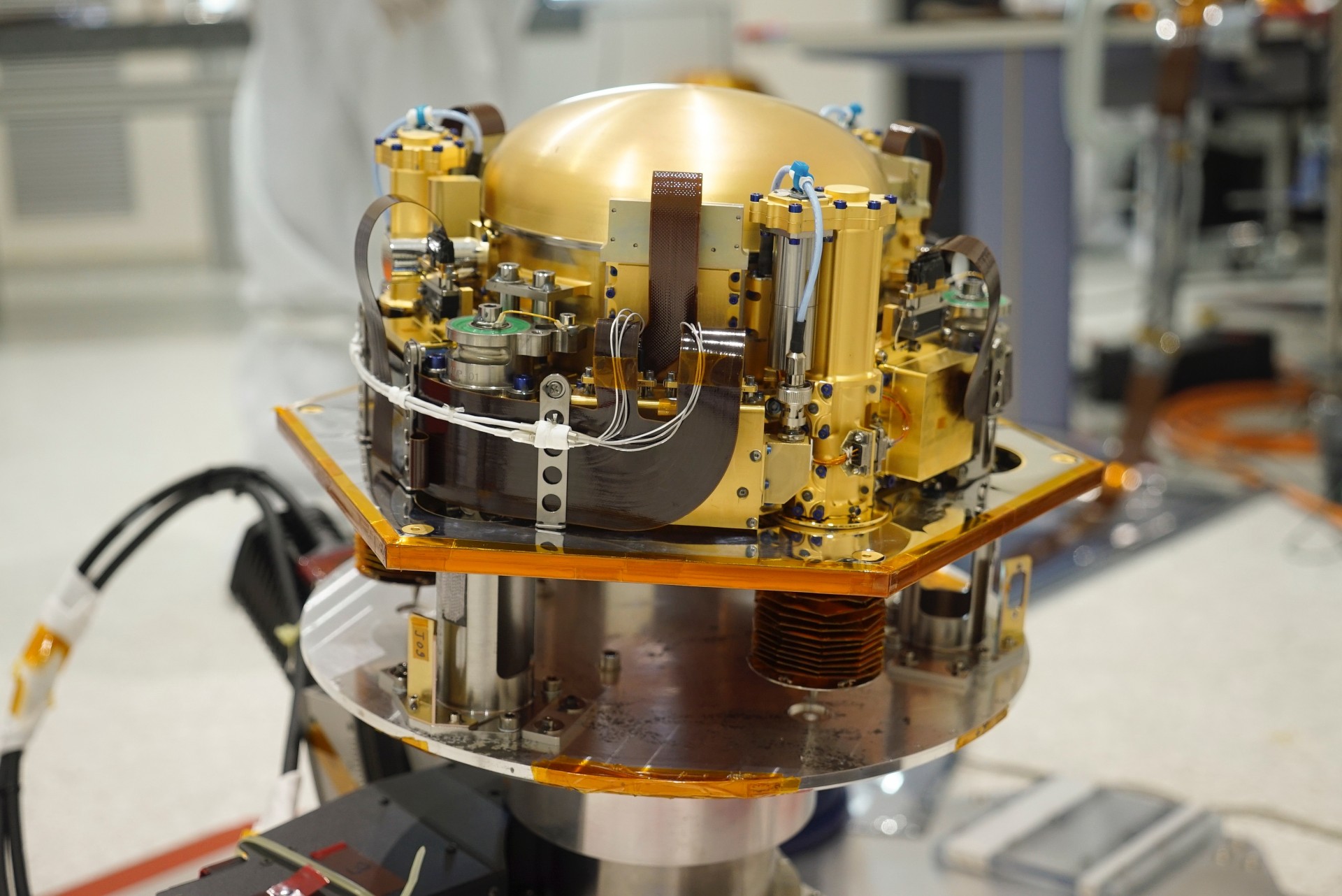
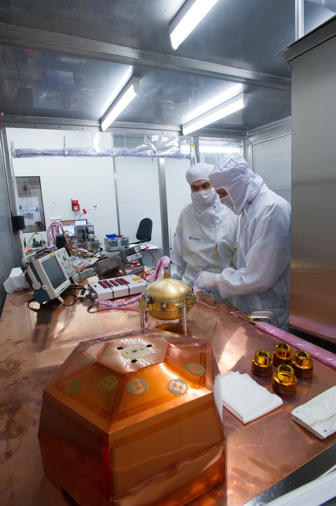
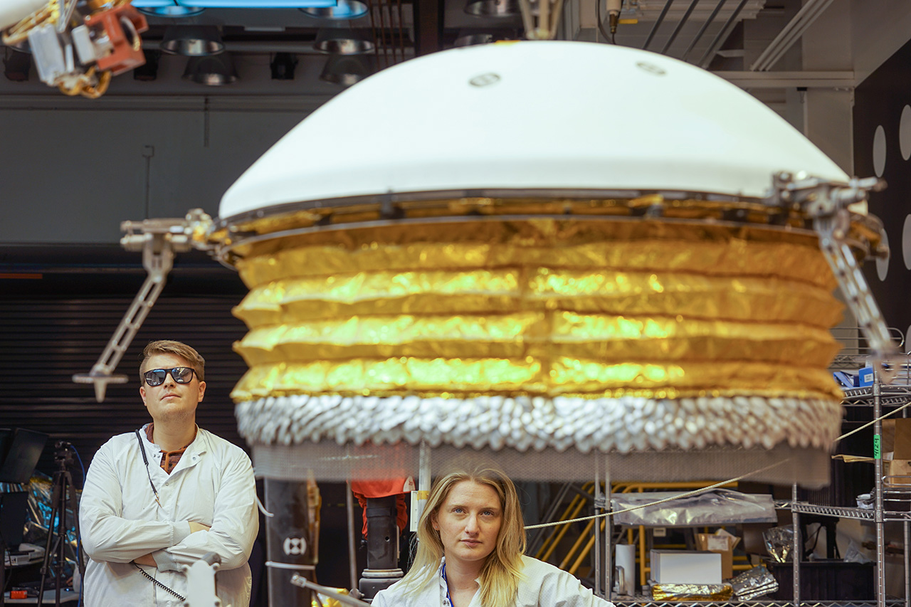
.") Removing the SEIS sphere from the gas-tight chamber (¬© Hervé Piraud/IPGP/SODERN/CNES).
Removing the SEIS sphere from the gas-tight chamber (¬© Hervé Piraud/IPGP/SODERN/CNES).
Space is an unforgiving place, and makes life complicated for SEIS.
The seismometer must not only continue to function but must also maintain its level of performance, i.e. its great sensitivity, after being subjected to assaults that would destroy any sophisticated seismometer designed solely for terrestrial use.
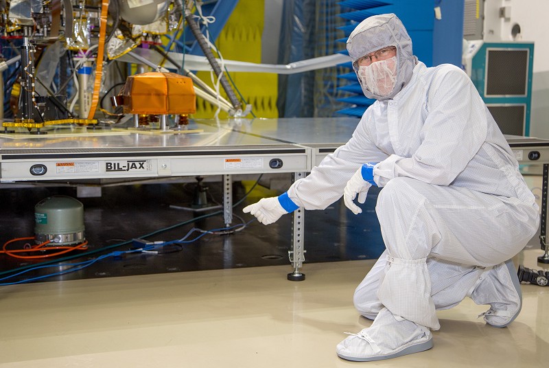
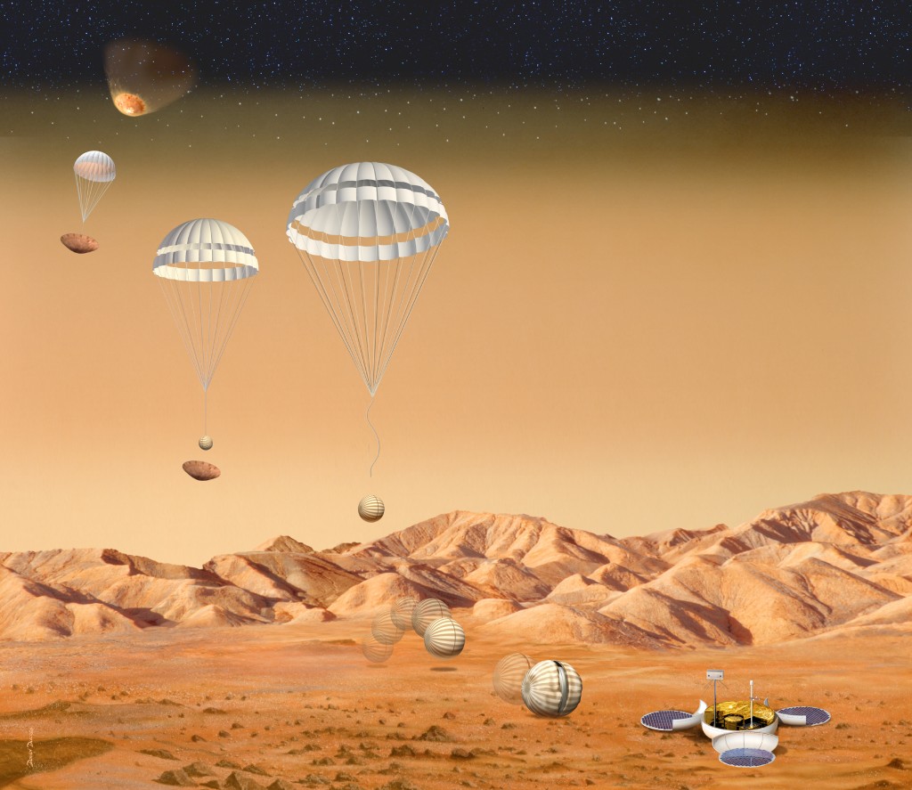
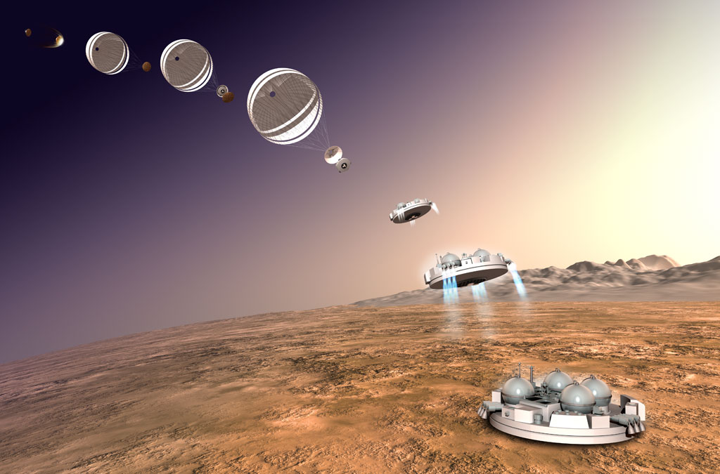
On lift-off, the seismometer will be have to endure short but extremely violent shocks or impacts, and will be jolted in all directions. The slightest fragility in the most delicate mechanisms could have disastrous consequences. On Earth, the ability to resist shocks and vibration (generally caused by the detonation of pyrotechnic devices over the course of the mission) is tested on instruments of torture known as shakers.
Compared with other instruments, the seismometer presents a sizeable challenge since, by definition, it comprises a moving part that has to move freely along a fixed part under the slightest motion. During critical phases such as lift-off or landing, there might be some advantage in locking the moving part, unlocking it only once it is on the ground.
Viking 1's inability in 1976 to disengage the seismometer pin means that this system is frowned on by engineers, and no locking system has therefore been used on the SEIS seismometer. The ability of the pendulums to withstand impacts and vibration relies on the fact that the moving part has very little play. Its displacement is limited to just a few tens of microns, though this does not prevent its being able to measure large magnitude tremors.
Temperatures and vacuum
The second feature of the space environment is the enormous temperature fluctuations. During the voyage from Earth to Mars, and once on the surface of the Red Planet, the SEIS seismometer will experience extreme changes in temperature. To check its thermal behaviour on Earth, the instrument is progressively taken to high temperatures in an oven (up to 60°C) before being placed in chambers at glacial temperatures down to -75°C. Some tests on the first models even went down below -100°C.
By definition, space is (almost) empty, and tests have therefore been carried out to check that the seismometer operates correctly in the complete absence of air. Using "Martian" chambers, project engineers check that the instrument is capable of withstanding the Martian atmosphere, i.e. CO2 at just a few mbar. This atmosphere—very different from that on Earth—can have some surprising effects on electronic systems, being conducive, for example, to electrical arcing.
Radiation and electromagnetic fields
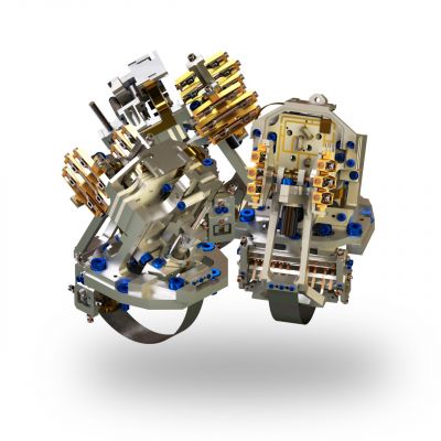
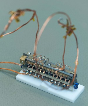
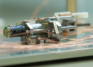
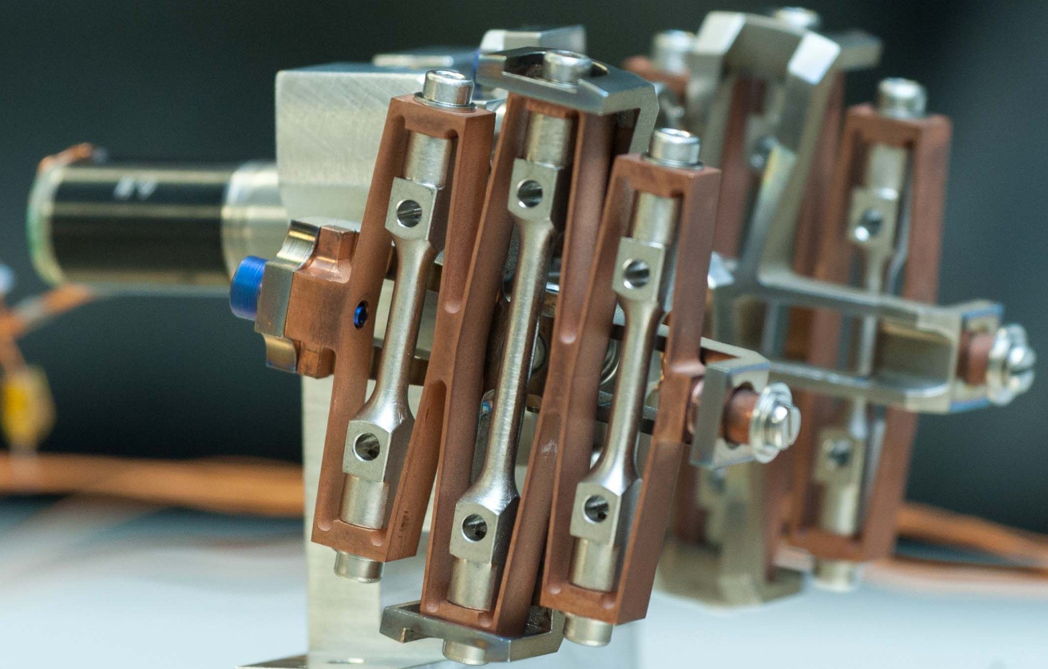
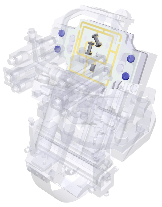
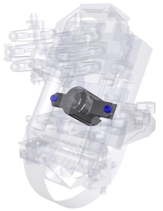
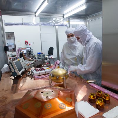
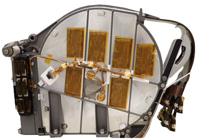
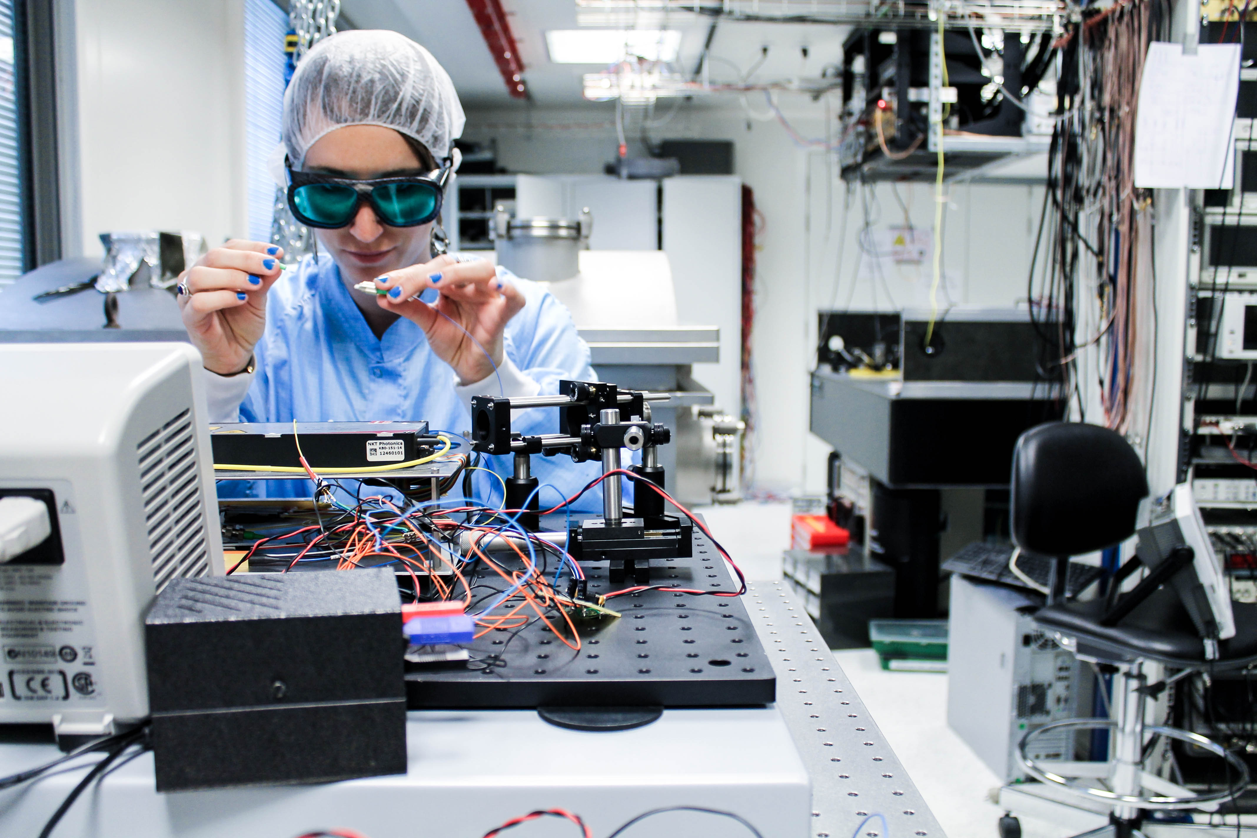
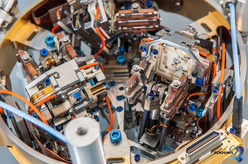
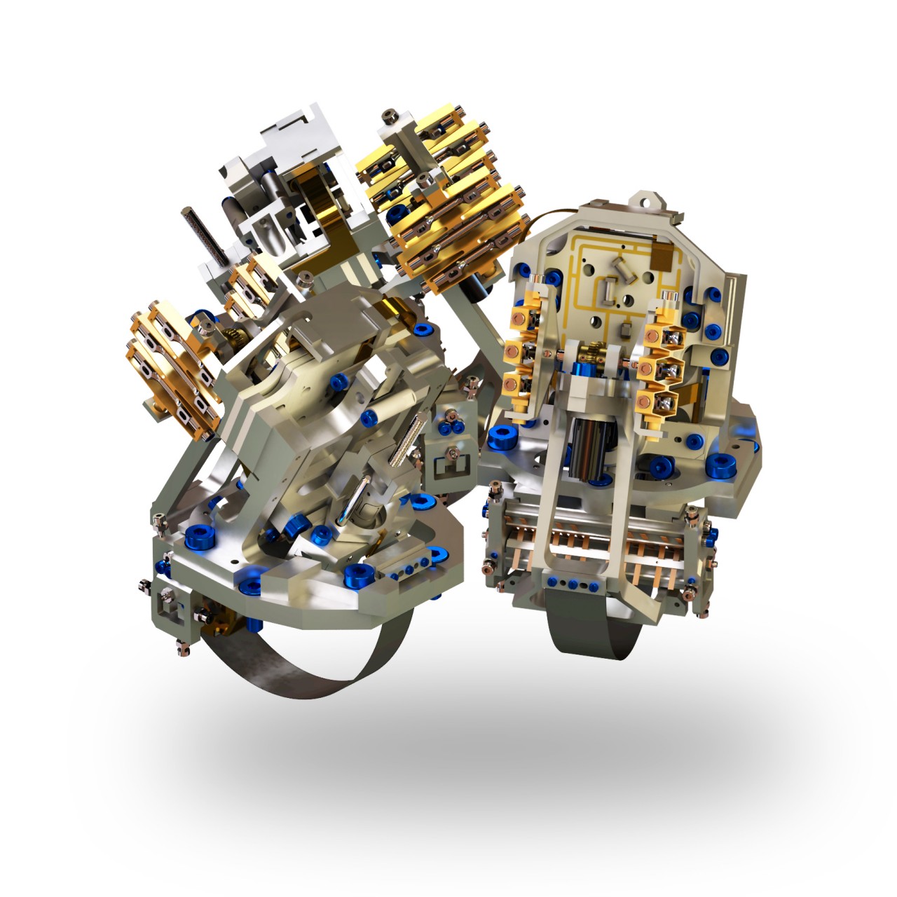
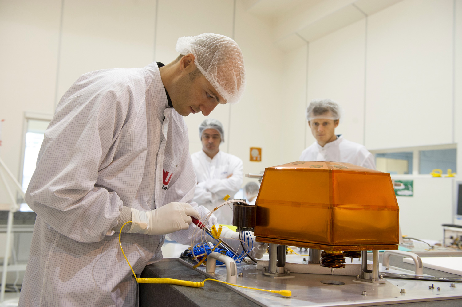
 Testing a VBB pendulum (© Patrice Latron/IPGP).
In the absence of an atmosphere and a deflecting magnetic field, space is bathed in harmful radiation from the Sun or galactic space. This radiation consists of highly energetic particles that can cause immense damage to electronic components.
The computer on which you are reading these words would almost immediately cease to function in space due to corruption of the RAM or registers in the central processor by cosmic rays or the solar wind. Batteries of tests must therefore be carried out to check that the SEIS seismometer is sufficiently hardened against radiation, whether on the flight from Earth to Mars or once on the Red Planet (where it will, however, be relatively protected by the planet's atmosphere).
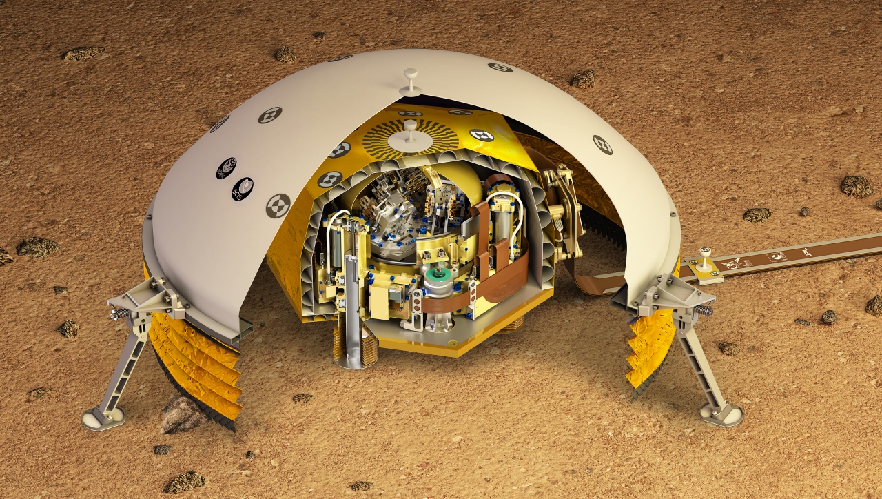
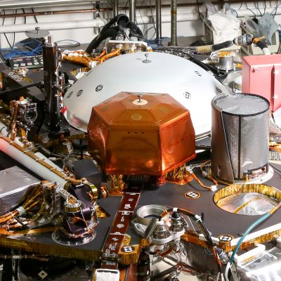
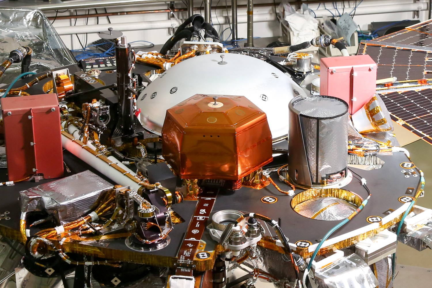
Finally, other tests aim to validate the operation of the seismometer when exposed to surrounding magnetic fields. Once on the Martian surface, the InSight lander's activity will generate its own magnetic fields. Here, for example, the most significant source is without a doubt the radio antennas, especially the UHF antenna which maintains communication with the US Mars Reconnaissance Orbiter. Tests have been conducted on Earth at the Toulouse Space Centre belonging to the French space agency, CNES, to check whether or not the seismometer is disturbed by the antenna in question when the latter is transmitting or receiving a radio signal.
Faced with this dizzying list, it is not hard to imagine the incredible amount of work the engineering teams who designed and developed the SEIS seismometer have had to do. Entire rooms could easily be filled with just the raw data, test reports, technical anomaly listings, reviews and summaries.
This is a price worth paying, however, for scientists to benefit from an instrument that can register and characterize the tiniest tremors of an extraterrestrial world hundreds of millions of kilometres from Earth.
Last updated: 26 October 2016
")


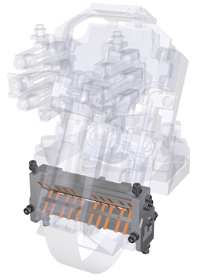
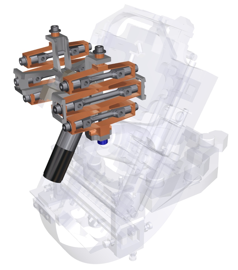
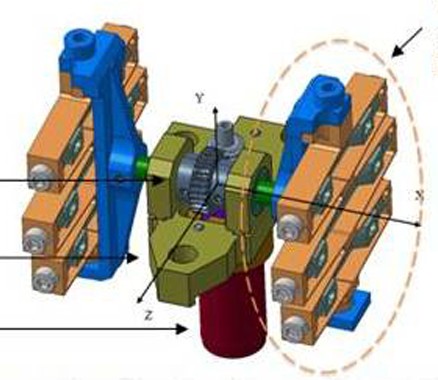
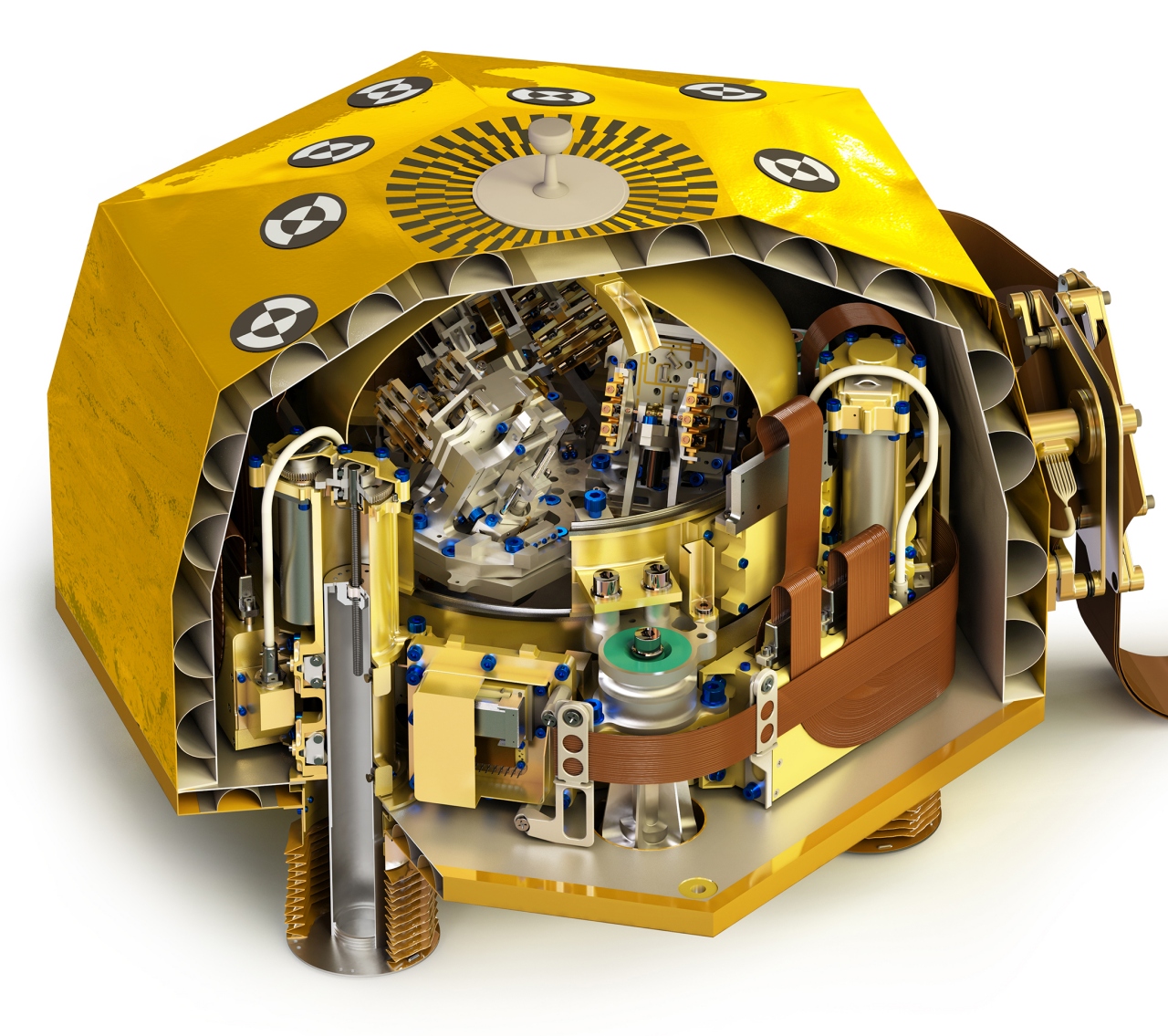
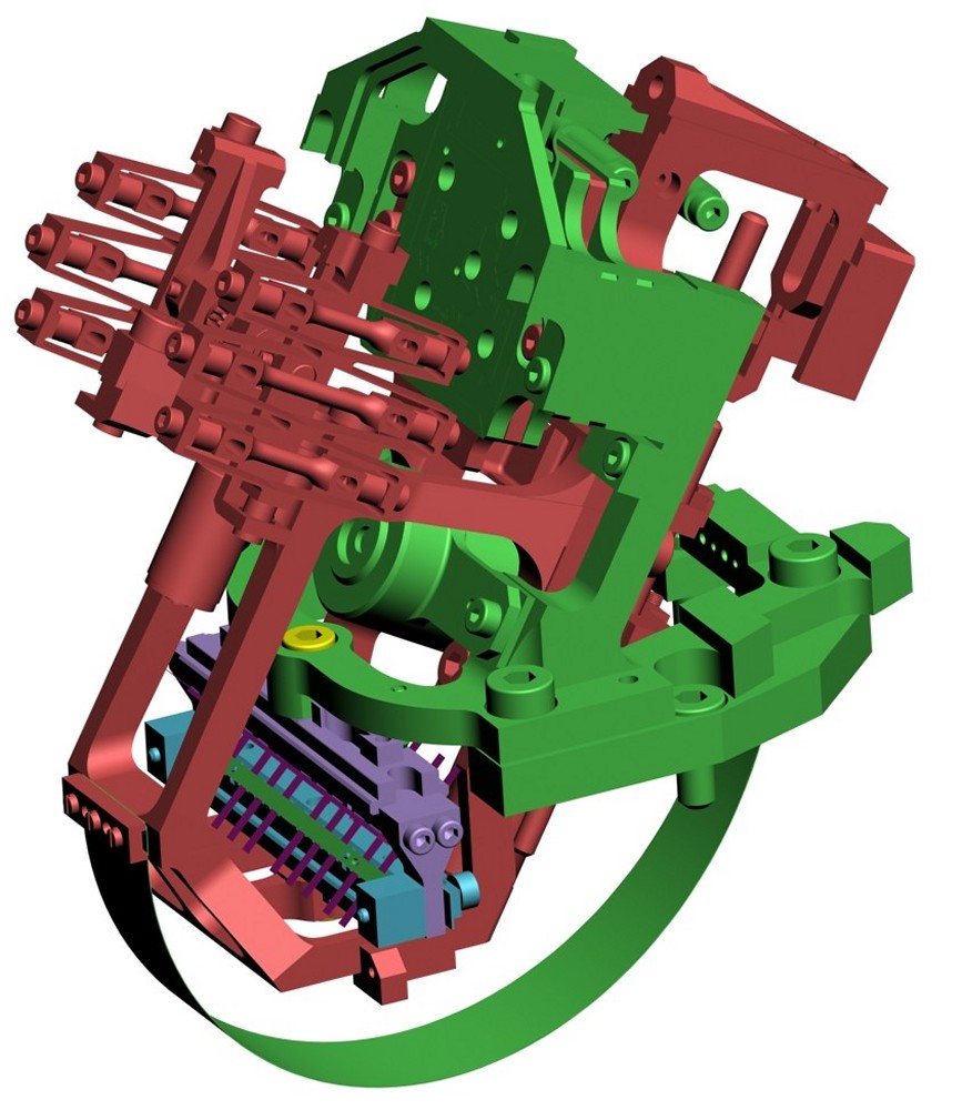
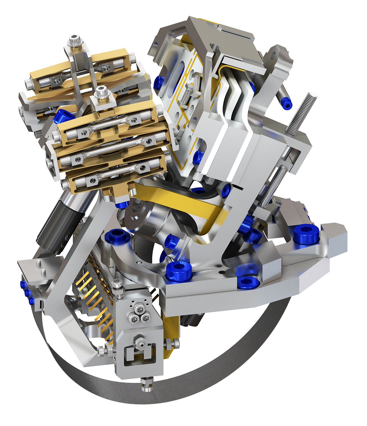
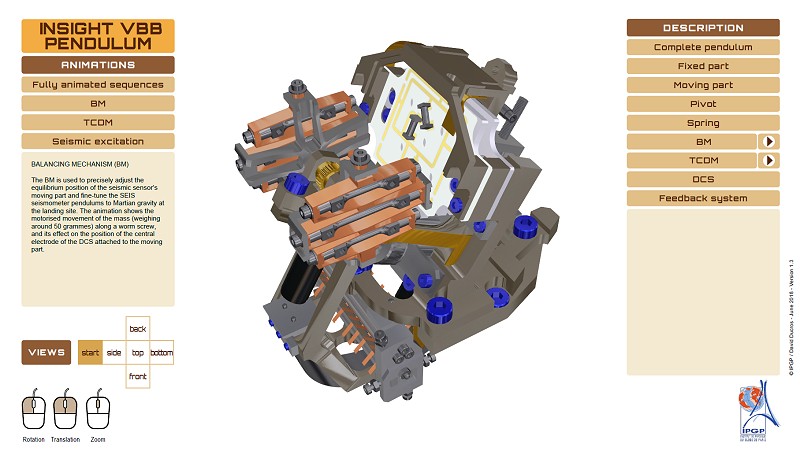 Interactively explore the structure of a VBB pendulum and find out how it works (interactive PDF file) (© IPGP/David Ducros).
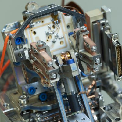


.")


.")
.")
.")
.")
")

")
.")
.")
.")
.")

.")

.")
")
.")
.")
.")

.")
 pendulum (© IPGP).")
.")
.")
.")